Crimp terminal, connection structural body and method for producing the same

a technology of connection structure and clamping terminal, which is applied in the direction of contact member manufacturing, liquid/solution decomposition chemical coating, coupling device connection, etc., can solve the problems of insufficient conductivity of connection structure body, galvanic corrosion, and aluminum conductor formed of less noble metal materials than metal materials, so as to prevent galvanic corrosion of aluminum substrate and high conductivity

Active Publication Date: 2016-04-19
FURUKAWA ELECTRIC CO LTD +1
View PDF21 Cites 15 Cited by
  • Summary
  • Abstract
  • Description
  • Claims
  • Application Information

AI Technical Summary

Benefits of technology

[0109]The present invention provides a crimp terminal, a connection structural body, and a method for producing the same, which, even when an electrolytic solution is directly attached to a surface of an aluminum substrate so that the electrolytic solution is present between the aluminum substrate and a conductive contact body containing a nobler metal material than an aluminum material, prevent galvanic corrosion of the aluminum substrate and thus provide high conductivity with another conductive member.

Problems solved by technology

However, a connection structural body, obtained by stripping a tip of an insulated wire of a conductor cover to expose a tip of an aluminum conductor and pressure-bonding the tip of the aluminum conductor to the above-mentioned terminal, has a problem that the aluminum conductor formed of an aluminum material less noble than the metal material used to form the terminal is corroded as a result of contact of the aluminum conductor and the terminal; namely, has a problem of galvanic corrosion.
This causes a problem that the connection structural body cannot exhibit a sufficient conducting function.
Thus, the problem of galvanic corrosion occurs between the main body of the terminal and the elastic piece.
Therefore, when an electrolytic solution such as water or the like is attached, the main body of the terminal itself is corroded.
This causes pitting corrosion or the like, and as a result, the elasticity of the elastic piece, and the mechanical strength and the like of the terminal itself cannot be maintained.
In addition, the conductor is corroded in the pressure-bonging section, which increases the electric resistance, and as a result, the conductor may undesirably lose functions thereof.
In addition, the technology proposed in Patent Documents 1 and 2 is difficult to be applied to the conventional processing procedure for producing a terminal, namely, a continuous procedure of punching out the substrate of the terminal with a press and bending the substrate.
Thus, it is difficult to mass-produce the terminal with the technology proposed in Patent Documents 1 and 2.
However, when an electrolytic solution is attached to a contact part where the crimp terminal formed of an aluminum substrate and the conductive contact body containing a nobler metal material than the aluminum material, there occurs a problem that galvanic corrosion occurs to the contact part of the crimp terminal formed of the aluminum substrate, which undesirably decreases the conductivity with the other conductive members.
In addition, in the case where a terminal to which the connection section is to be connected is an aluminum terminal, or in the case where a wire conductor to which the pressure-bonding section is to be pressure-bonded is an aluminum terminal, there occurs a problem that the above-mentioned conductive contact body used to cover at least the surface of the connection section or the pressure-bonding section of the crimp terminal causes galvanic corrosion of the aluminum wire conductor and the aluminum terminal.

Method used


Image

  • Crimp terminal, connection structural body and method for producing the same
  • Crimp terminal, connection structural body and method for producing the same
  • Crimp terminal, connection structural body and method for producing the same

Examples


embodiment 1

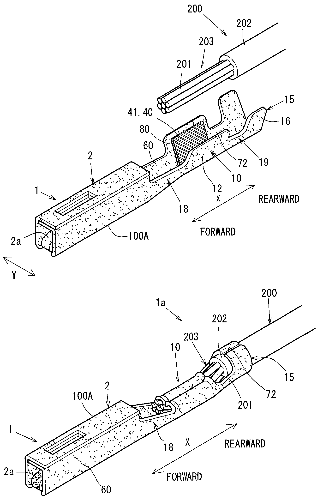
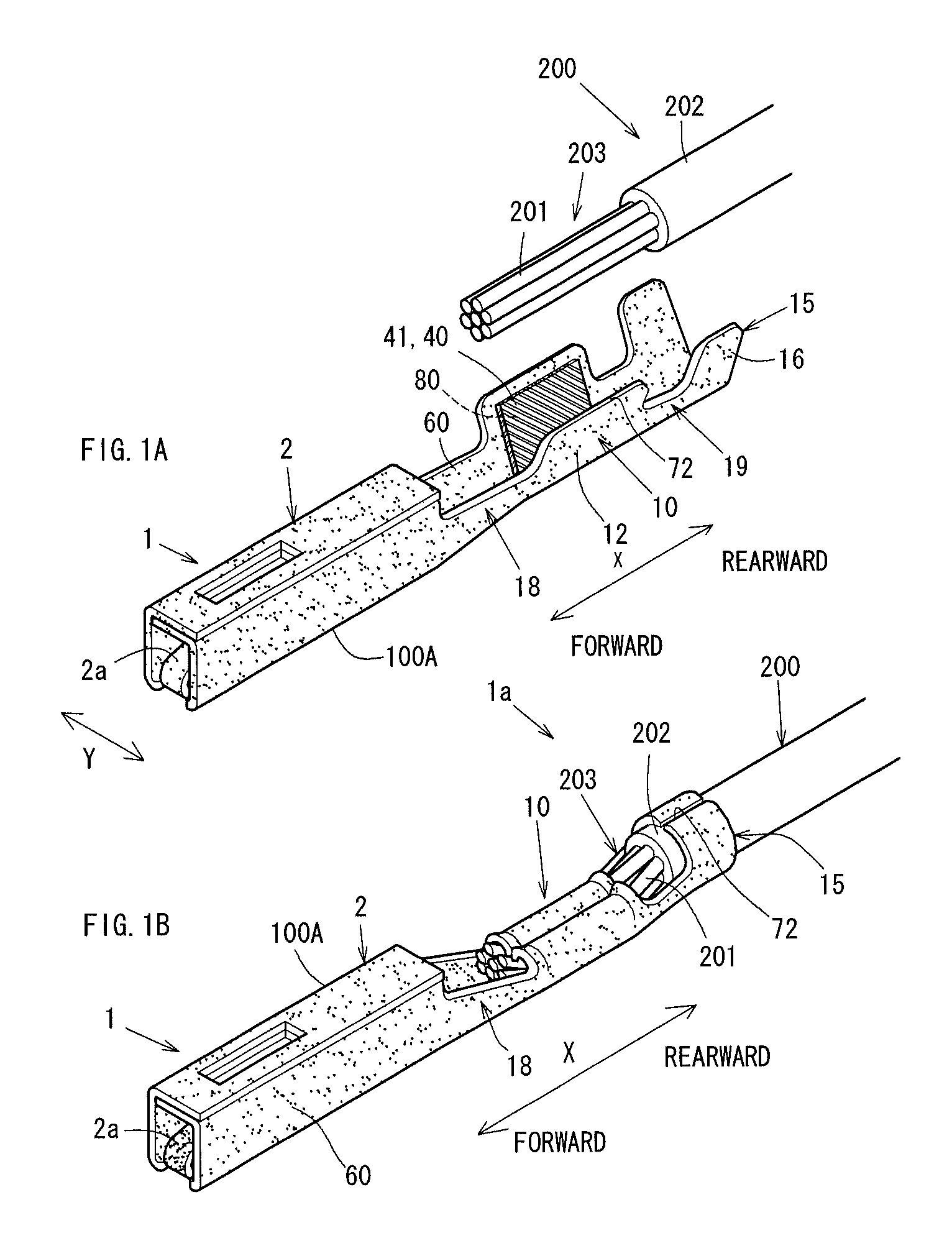
[0138]FIG. 1 shows isometric views of the crimp terminal 1 and the connection structural body 1a in Embodiment 1. FIG. 2 shows the crimp terminal 1, and FIG. 3 shows a plate-like aluminum plate 100 used to form the crimp terminal 1.

[0139]In more detail, FIG. 1A is an isometric view of the crimp terminal 1 and an insulated wire 200 which is before pressure-bonded to the crimp terminal 1 in Embodiment 1. FIG. 1B is an isometric view of the connection structural body 1a.

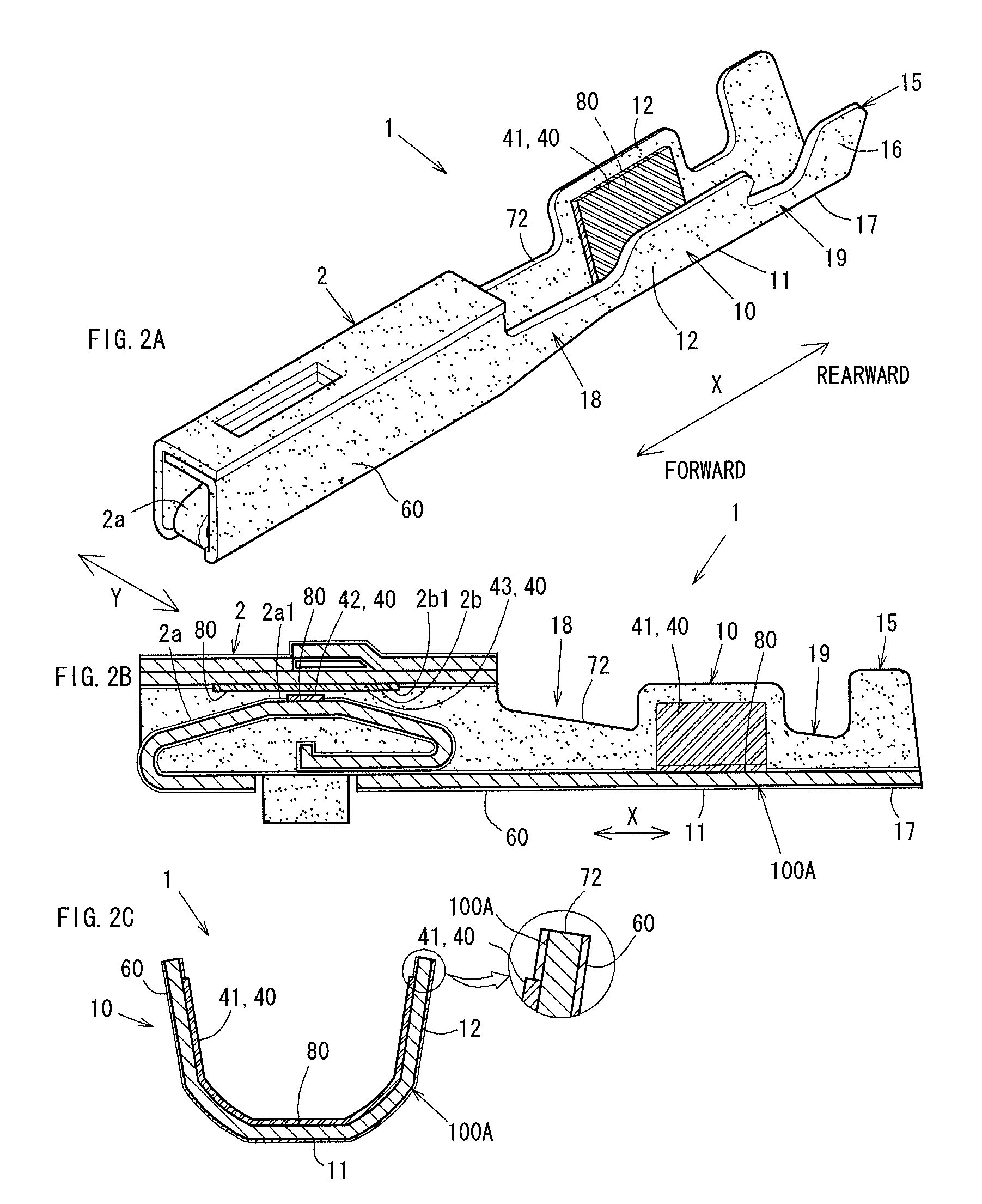
[0140]FIG. 2A is an isometric view of the crimp terminal 1. FIG. 2B is a vertical cross-sectional view of the crimp terminal 1 taken along a line extending in a longitudinal direction at an intermediate position in a width direction Y. FIG. 2C is a cross-sectional view of the wire barrel section 10 of the crimp terminal 1 taken along a line extending perpendicularly to the longitudinal direction.

[0141]FIG. 3A is a partial plan view of the plate-like aluminum plate 100 which is to be processed into the crimp terminal 1,...

embodiment 2

[0178]As shown in FIG. 4 and FIG. 5, the crimp terminal 1A in Embodiment 2 includes the anodized film 60 formed also on the press-sheared edge 72 of the aluminum substrate 100A obtained as a result of press shearing.

[0179]The connection structural body 1Aa in Embodiment 2 includes the crimp terminal 1A connected to the insulated 200 in substantially the same manner as in Embodiment 1.

[0180]FIG. 4A is an isometric view of the connection structural body 1Aa in Embodiment 2, FIG. 4B is an isometric view of the crimp terminal 1A in Embodiment 2, and FIG. 4C is a cross-sectional view of the wire barrel section 10 of the crimp terminal 1A taken along a line extending perpendicularly to the longitudinal direction. FIG. 5 shows a step of a method for producing the crimp terminal 1A. In more detail, FIG. 5A is a plan view of the reel terminal 90 described later, and FIG. 5B is a cross-sectional view taken along line A-A of FIG. 5A. FIG. 6 shows a step of another method for producing the crim...

embodiment 3

[0196]As shown in FIG. 7A and FIG. 7B, the connection structural body 1Ba in Embodiment 3 includes a crimp terminal 1B which is substantially the same as the crimp terminal 1A in Embodiment 2 and the insulated wire 200. The aluminum conductor tip part 203 of the insulated wire 200 is connected to the wire barrel section 10 of the crimp terminal 1B by pressure bonding. The anodized film 60 is formed on the crimp terminal 1B including the press-sheared edge 72 but excluding the contact parts 80 and on the aluminum conductor tip part 203.

[0197]FIG. 7A is an external view of the connection structural body 1Ba in Embodiment 3, and FIG. 7B is a vertical cross-sectional view taken along a line extending in the longitudinal direction at an intermediate position of the connection structural body 1Ba in the width direction.

[0198]The connection structural body 1Ba in Embodiment 3 is not limited to having the structure in which the crimp terminal 1A in Embodiment 2 is connected to the insulated...


PUM

PropertyMeasurementUnit
temperatureaaaaaaaaaa
widthaaaaaaaaaa

Abstract

An insulating body-forming part is formed on a border between a surface of a crimp terminal formed of an aluminum material and a conductive contact body provided on the surface and containing a nobler metal material than the aluminum material.

Description

TECHNICAL FIELD[0001]The present invention relates to a crimp terminal attachable to, for example, a connector or the like for connection of a wire harness for an automobile, a connection structural body including the same, and a method for producing the same; and in more detail, to a crimp terminal connectable to a wire harness and formed of an aluminum material, a connection structural body including the same, and a method for producing the same.BACKGROUND ART[0002]Today, carbon dioxide emissions from automobiles are required to be reduced. Since reduction of weight of vehicles greatly influences improvement of fuel efficiency, the weight of wire harnesses for connecting electrical components are also required to be reduced. Therefore, it has been studied to, for example, replace copper-based materials which are conventionally used for electric wires or the like used for the wire harnesses with an aluminum material and such an aluminum material has been used for some electric wire...

Claims


Application Information

Patent Timeline
Patent Type & Authority Patents(United States)
IPC IPC(8): H01R4/18C23C18/54C25D11/24C25D11/04H01R13/03H01R43/048H01R43/16C25D11/02H01R13/11C25D11/08
CPCH01R4/183C23C18/54C25D11/022C25D11/04C25D11/08C25D11/246H01R4/185H01R13/03H01R43/048H01R43/16H01R13/111Y10T29/4921Y10T29/49218
Inventor MITOSE, KENGOTAKASHIMA, NAOYAKAWAMURA, YUKIHIRO
Owner FURUKAWA ELECTRIC CO LTD
Why Eureka
Try Eureka