
Press-in pin for an electrical press-in connection between an electronic component and a substrate plate

a technology of press-in pin and electronic component, which is applied in the direction of coupling contact member, securing/insulating coupling member, electrical apparatus, etc., can solve the problems of short circuits that cannot be tolerated by electronic components such as abs or esp circuits in motor vehicles, tin-lead alloys in press-in tin coatings, etc., and achieves sufficient long-term stability, increase processing temperature, and the effect of ensuring the long-term stability

Active Publication Date: 2016-05-03
ROBERT BOSCH GMBH
View PDF12 Cites 4 Cited by
  • Summary
  • Abstract
  • Description
  • Claims
  • Application Information

AI Technical Summary

Benefits of technology

The invention provides a press-in pin with a locking mechanism that prevents whisker formation, which is a long term stability issue. The press-in pin is coated with a metal alloy and a tin alloy of the press-in pin head forms a materially bonded, frictional connection with the metal alloy of the contact hole. The press-in pin collar with the locking projection ensures electrical insulation and protection from whisker formation. The cross section of the press-in pin head is designed to cause a cold friction weld with a round metallic contact hole. The insulating coating eliminates the need for intermediate layers to suppress whisker formation and prevents electron and ion transport. This results in a long term stable press-in connection.

Problems solved by technology

This entails the risk that the thread-like monocrystalline whiskers that are several millimeters long cause short circuits on the substrate plate, in particular between adjacent contact regions, which short circuits cannot be tolerated by electronic components such as ABS or ESP circuits in motor vehicles.
On account of considerations regarding recycling and environmental protection, the tin-lead alloys in tin coatings of a press-in pin, which prevent whiskers from forming, are however also not tolerable, in particular in the case of motor vehicle components which are increasingly intended to be recycled.
This not only has the disadvantage of an additional, complicated and also expensive (due to the precious metal) further deposition step but can also lead to problems of solderability of the tin coating when the deposited layer is too thick.
In the case of this disclosed connecting piece, the whisker formation on tin coatings is prevented by a subsequent resin coating of the copper-tin connection; however, a whisker formation is not thereby prevented after the tin coated press-in pin of an electronic component has been pressed into a contact hole of a substrate plate.

Method used


Image

  • Press-in pin for an electrical press-in connection between an electronic component and a substrate plate
  • Press-in pin for an electrical press-in connection between an electronic component and a substrate plate
  • Press-in pin for an electrical press-in connection between an electronic component and a substrate plate

Examples


Embodiment Construction

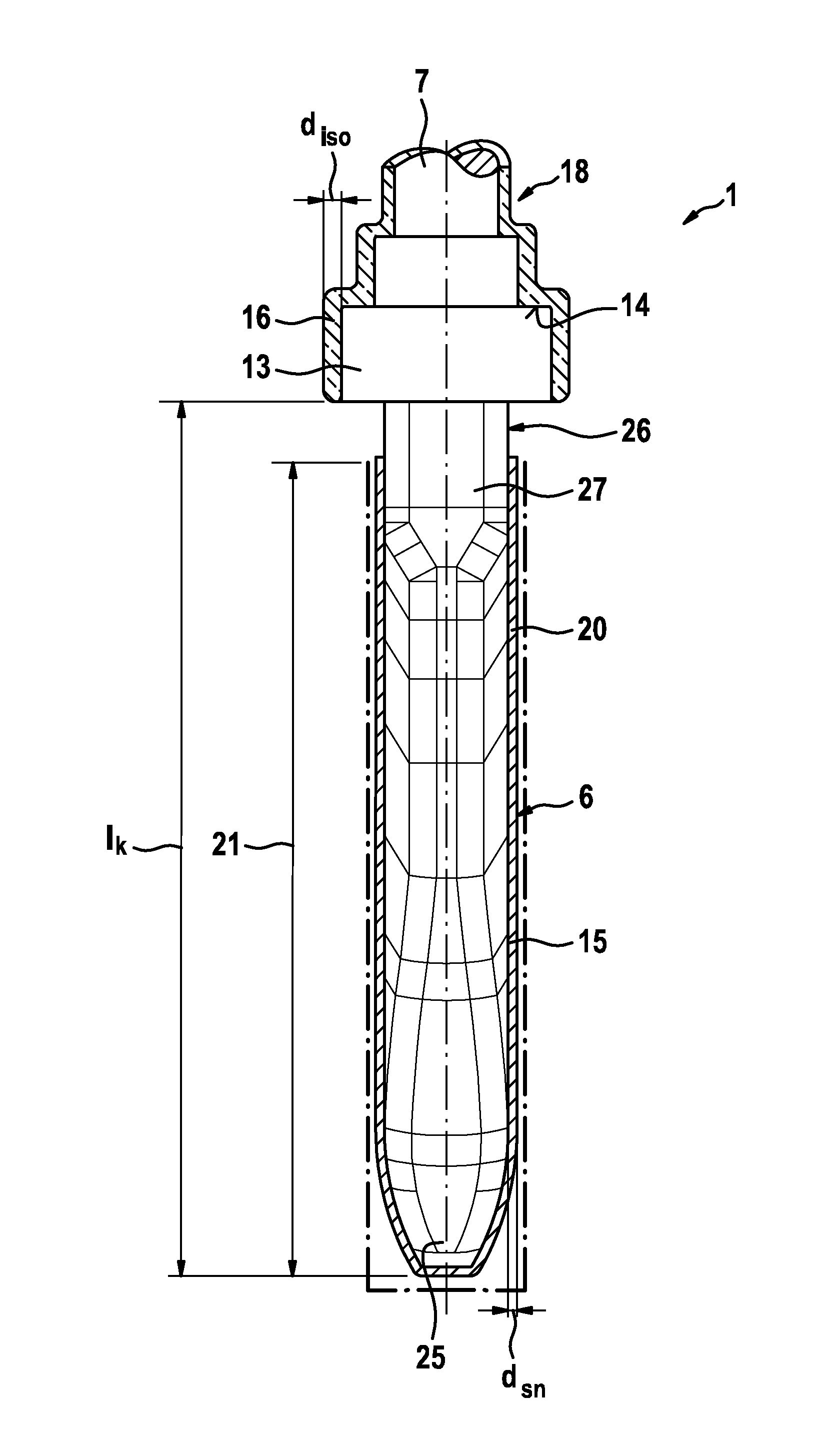
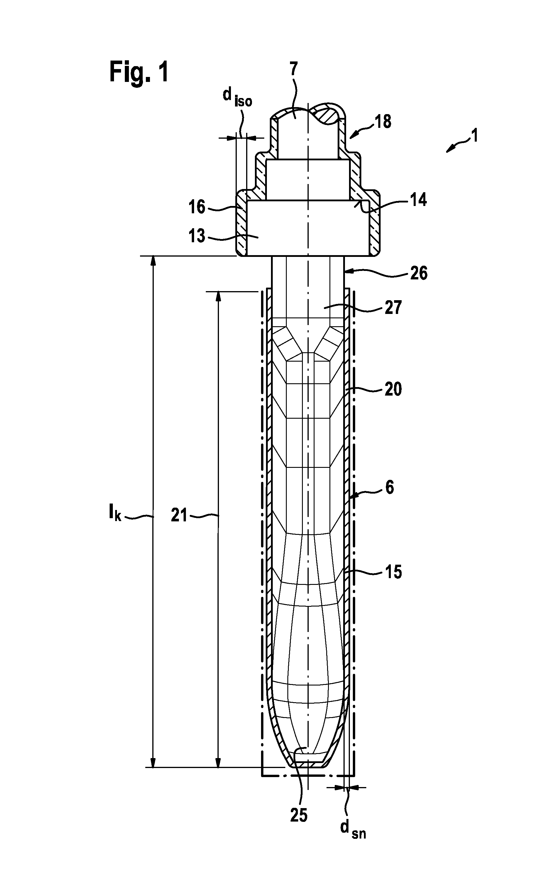
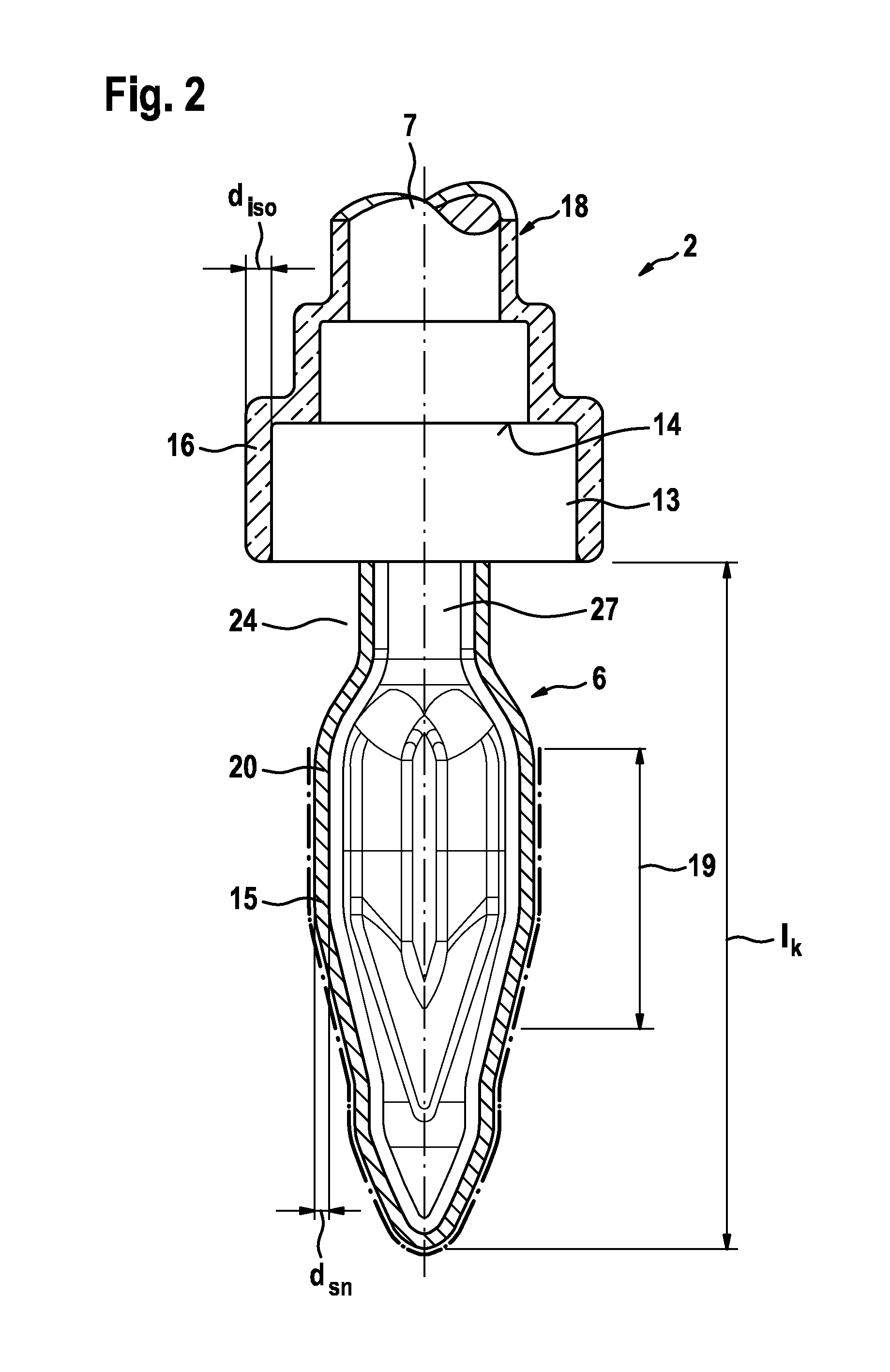
[0023]FIG. 1 shows a schematic view of a press-in pin head 6 of a press-in pin 1 according to a first embodiment of the invention. The press-in pin head 6 has a length IK which is matched to the thickness of a substrate plate depicted in FIG. 4. In this first embodiment of FIG. 1, the tip 25 of the press-in pin 6 has an oval shape in the longitudinal section thereof, the cross section of which is matched to an interference fit to a metalized contact hole of the substrate plate shown in FIG. 4. The oval tip then transitions into a shape having a polygonal cross section. A massive press-in zone 21 extends approximately over the entire length IK of the press-in pin head 6 and is covered by a layer 20 consisting of a tin alloy 15, which has a thickness between 5 μm≦dSn≦50 μm and a tin content [Sn] between 90 wt %≦[Sn]≦100 wt %.

[0024]A press-in pin collar 13 adjoins the press-in pin head 6, which collar transitions via a locking projection or, respectively, a press-in pin shoulder 14 int...


PUM


Abstract

The invention relates to a press-in pin (1, 2) for an electrical press-in connection between an electronic component (3) and a substrate plate (4) with an electrical contact hole (5). The press-in pin (1, 2) has a press-in pin head (6) which has a press-in head length (IK) which is matched to a thickness (d) of the substrate plate (4). A press-in pin leg (7) extends between the electronic component (3) and the press-in pin head (6). A press-in pin collar (13) forms a transition between the press-in pin leg (7) and the press-in pin head (6) and has a locking projection (14). The press-in pin head (6) is coated with a layer (20) of a lead-free tin alloy (15). At least the press-in pin collar (13) with the locking projection (14) has an electrically insulating coating (16).

Description

BACKGROUND OF THE INVENTION[0001]The invention relates to a press-in pin for an electrical press-in connection between an electronic component and a substrate plate with an electrical contact hole.[0002]A press-in zone of such a press-in pin is usually covered with a tin layer which forms a low-resistance metallic contact when pressed into a metalized contact hole of the substrate plate. Lead-free tin alloys comprising a tin content of over 90 wt % tend to relieve mechanical stresses by the transport of ions while forming thread-like monocrystalline whiskers. This entails the risk that the thread-like monocrystalline whiskers that are several millimeters long cause short circuits on the substrate plate, in particular between adjacent contact regions, which short circuits cannot be tolerated by electronic components such as ABS or ESP circuits in motor vehicles. On account of considerations regarding recycling and environmental protection, the tin-lead alloys in tin coatings of a pre...

Claims


Application Information

Patent Timeline
Patent Type & Authority Patents(United States)
IPC IPC(8): H01R13/03H01R12/58H01R13/41
CPCH01R13/03H01R12/585H01R13/41
Inventor MOSER, MANFRED
Owner ROBERT BOSCH GMBH
Learn More