Network packet timing synchronization for virtual machine host systems

a virtual machine host system and network packet technology, applied in the field of network packet communication systems, can solve the problems of large timing errors, high variability of vm platforms, and reduce the accuracy of ntp/ptp

Active Publication Date: 2016-05-17
KEYSIGHT TECH SINGAPORE (SALES) PTE LTD
View PDF15 Cites 21 Cited by
  • Summary
  • Abstract
  • Description
  • Claims
  • Application Information

AI Technical Summary

Problems solved by technology

Further, clock ticks for the virtualized CPU 208A typically have significant variations leading to large timing errors.
Because NTP / PTP depends on symmetric and consistent network delays, the high variability for the VM platforms 206A-C reduce accuracy for NTP / PTP.
The virtual machine environment, therefore, creates significant inaccuracies with respect to timing synchronization.
These variable unknown delays create errors in timing synchronization that cause the VM host hardware system 300 to be unacceptable for timing sensitive applications.

Method used


Image

  • Network packet timing synchronization for virtual machine host systems
  • Network packet timing synchronization for virtual machine host systems
  • Network packet timing synchronization for virtual machine host systems

Examples


embodiment 300

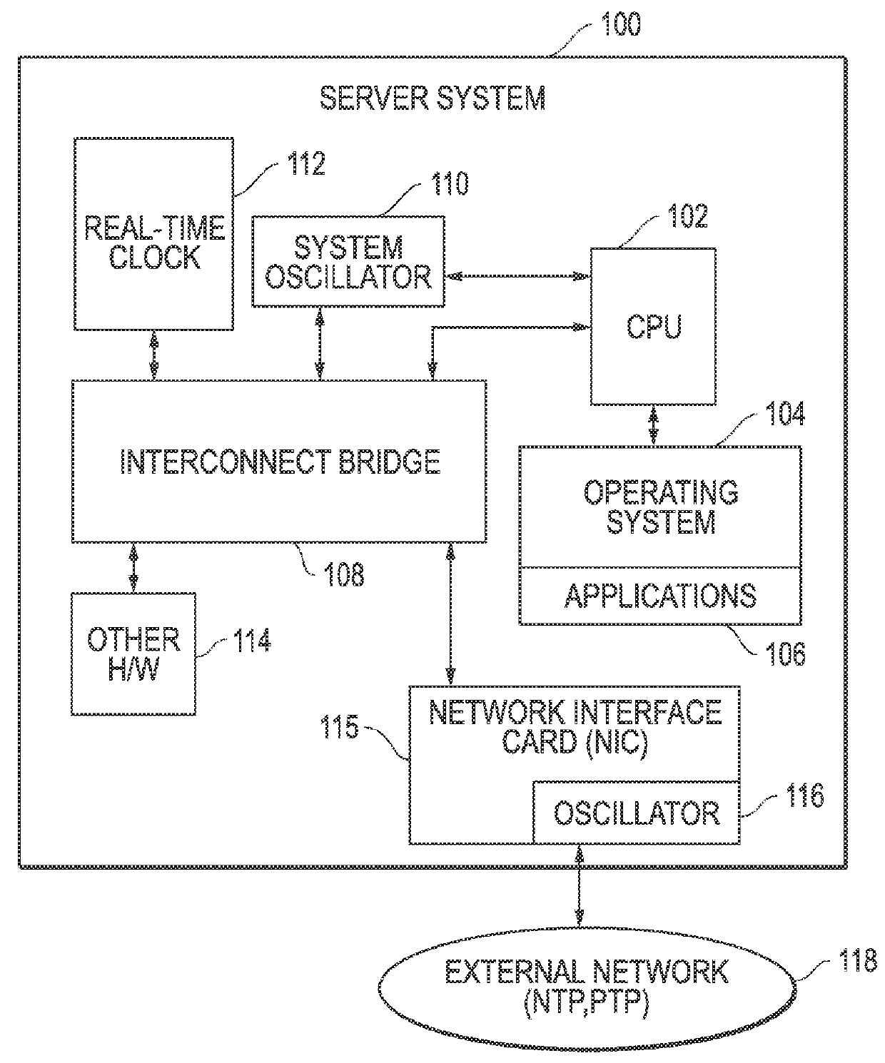
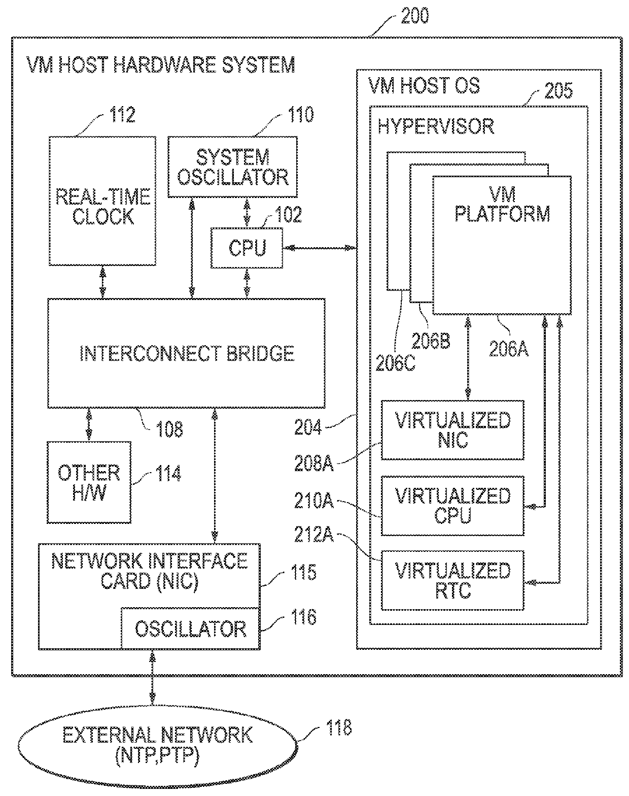
[0055]In part, the VM host hardware system 400 operates in a similar fashion to embodiment 300 of FIG. 3 (Prior Art). The VM host hardware system 400 includes a central processing unit (CPU) 102 that runs a host operating system 204, a system oscillator 110, a real-time clock 112, a network interface card (NIC) 115, and other hardware (H / W) 114 coupled to communicate with the CPU 102 through an interconnect bridge 108. The NIC 115 can also include an oscillator 116, and the system oscillator 110 can also be directly connected to the CPU 102. The real-time clock 112 can be implemented using an integrated circuit including a real time clock (RTC) circuitry and non-volatile read only memory (RTC / NVRAM). The VM host hardware system 400 also includes a hypervisor 205 that executes as part of the virtualization layer 302 on top of the VM host operating system (OS) 204. This hypervisor 205 provides access to a plurality of VM platforms 206A, 206B, 206C, and 206D that emulate processing sys...

embodiment 400

[0057]As described above, the virtual switch 404 provides virtual network packet communications among the VM platforms 206A, 206B, 206C, and 206D that are hosted as guest processes within the host operating system 204. In particular, the virtual switch 404 communicates with the virtualized NICs 208A, 208B, 208C, and 208D for the VM guest platforms 206A, 206B, 206C, and 206D to forward network packets among the VM guest platforms 206A, 206B, 206C, and 206D and between the VM guest platforms 206A, 206B, 206C, and 206D and the external network 118. As described above, the virtual switch 404 can operate using the system oscillator 110. However, with respect to embodiment 400 for FIG. 4, the virtual switch also has access to the hardware real-time clock (RTC) 112 through communication link 405. As also described herein, the transparent clock 402 allows for determination of intra-switch delays for packets traversing the virtual switch 404 and thereby allows for correction of timing inform...

embodiment 590

[0067]FIG. 5E is a diagram of an example embodiment for a new network packet 590 generated by the virtual switch 404 to provide intra-switch delay information. For the embodiment shown, the network packet 590 includes a source identifier (SID) field 591, a target identifier (TID) field 592, and one or more additional fields 593. The new network packet 590 also includes a field 594 for the residence time value. When a packet is communicated through the external network 118, a timestamp value is added to the timestamp field 558 to indicate the current time at the sending system. For embodiment 590, the residence time value (RTV) determined by the packet residence timer 532 is added to the field 594 within the new packet 590 to account for the intra-switch time delay associated with the packet as it traverses the virtual switch 404.

[0068]It is noted that FIGS. 5B-E provide example embodiments of techniques to communicate the intra-switch delay information from the virtual switch 404 to...


PUM


Abstract

Network timing synchronization for virtual machine (VM) host systems and related methods are disclosed that provide synchronization of master / slave clocks within VM host hardware systems. Master timing messages are sent from the master clocks to slave clocks within VM guest platforms hosted by the VM host hardware system within a virtualization layer, and return slave timing messages are communicated from the VM guest platforms to the master clock. Virtual switches within the virtualization layer use virtual transparent clocks to determine intra-switch delay times for the timing packets traversing the virtual switch. These intra-switch delay times are then communicated to target destinations and used to account for variations in packet transit times through the virtual switch. The VM guest platforms synchronize their timing using the timing messages. The master / slave timing messages can be PTP (Precision Time Protocol) timing messages and / or timing messages based upon some other timing protocol.

Description

TECHNICAL FIELD OF THE INVENTION[0001]This invention relates to network packet communication systems and, more particularly, to timing synchronization for network packets communicated within virtual machine host systems.BACKGROUND[0002]Network-connected computing systems often utilize network packets for communications within network communication systems. Timing information related to these network packet communications is often useful so that network nodes can synchronize their own operations, synchronize their operations with other network nodes, and / or determine relative time differences between internal or external events. Timing information can be obtained using a variety of techniques. For example, timing protocols can use GPS (Global Positioning System) or other GNSS (Global Navigation Satellite System) timing signals that are determined using GPS or GNSS receivers. Time code communication formats such as TRIG (inter-range instrumentation group) can also be used to transfer ...

Claims


Application Information

Patent Timeline
Patent Type & Authority Patents(United States)
IPC IPC(8): H04L12/46H04L7/00H04J3/06
CPCH04L7/0008H04L12/4641H04J3/0667H04J3/0682H04J3/0697G06F1/14H04L12/4633
Inventor KARNES, JOSHUA D.
Owner KEYSIGHT TECH SINGAPORE (SALES) PTE LTD
Why Eureka
Try Eureka