
Method and apparatus for denenoxing waste gases from nitration

a waste gas and nitration technology, applied in the field of denenoxing waste gases from nitration, can solve the problems of ineffective waste gas method, high cost, and inability to efficiently use the method for waste gases

Active Publication Date: 2016-05-24
COVESTRO DEUTSCHLAND AG +1
View PDF9 Cites 8 Cited by
  • Summary
  • Abstract
  • Description
  • Claims
  • Application Information

AI Technical Summary

Benefits of technology

wherein the reduction chamber is operated at a temperature of 800 to 1700° C. for the at least partial reduction of the NOx concentration.

Problems solved by technology

This process is used for the production of nitric acid on an industrial scale, hut is costly and, because of the volatile compounds comprised in the waste gas from nitration, is only suitable when combined with an oxidising combustion.
A less technically complex alternative is absorption in more chemically reactive systems, such as dilute sodium hydroxide solution, but: this has the disadvantage that an additional waste substance is obtained which requires treatment.
However, this method cannot be used efficiently for the waste gases from nitration in question since, with the high NOx concentrations in the waste gases, the exothermicity of the reduction reaction, e.g. according to the following reaction equation
In addition, the desired limit values cannot be reliably met because of the limited efficiency of the SNCR method.
As a result of the high exothermicity and the associated temperature increase, undesirable secondary reactions, such as the reaction 4 NH3+5 O2→4 NO+6 H2O, gain significance and mean that this method cannot be applied efficiently.
This method can therefore only be used for low NOx concentrations but not for waste gases from nitration.
A multi-stage execution with intermediate cooling is costly in terms of apparatus and is therefore uneconomical for the present application.

Method used


Image

  • Method and apparatus for denenoxing waste gases from nitration

Examples


Embodiment Construction

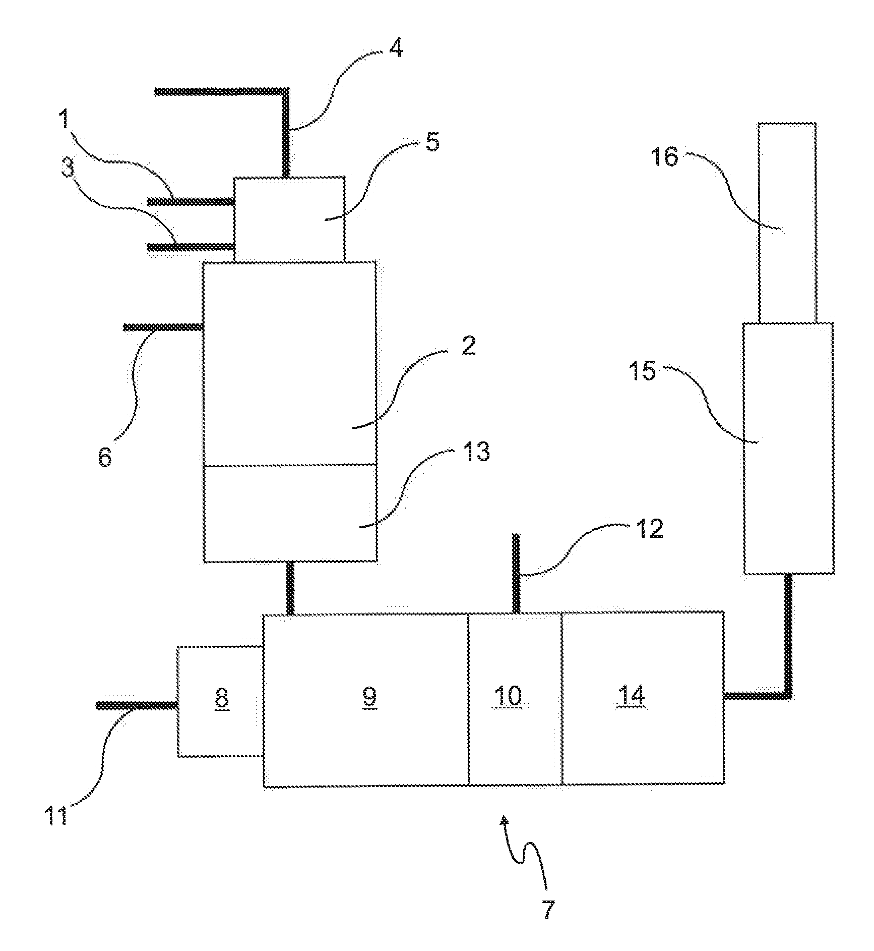
[0025]The present invention is based on the finding that the hydrogen-rich waste gas stream obtained during the hydrogenation of the organic nitro compounds can be separated out and reacted with the NOx-containing waste gas stream. In this way, not only are the nitrogen oxides, such as NO, NO2and N2O, eliminated from the NOx-containing waste gas stream but at the same time the quantity of the hydrogen-containing waste gas stream obtained, which would otherwise require separate disposal, e.g. by combustion, is reduced. The hydrogen-containing waste gas stream often comprises other volatile by-products of the hydrogenation reaction in addition to hydrogen, such as e.g. ammonia or aliphatic amines, which can also react with the nitrogen oxides at the reaction temperatures according to the invention.

[0026]Depending on how high the hydrogen concentration is in the hydrogen-containing waste gas stream, the method according to the invention can be implemented without the use of additional ...


PUM

PropertyMeasurementUnit
temperatureaaaaaaaaaa
temperaturesaaaaaaaaaa

Abstract

The invention relates to a method for reducing the concentration of nitrogen oxides in waste gases released dating the production of organic amino compounds, wherein an organic compound is first reacted with NOx and / or nitric acid to form an organic nitro compound with the formation of an NOx-containing waste gas stream and the organic nitro compound is converted to the organic ammo compound by means of hydrogen-containing reaction gas, the reaction of the organic nitro compound with the hydrogen-containing reduction gas taking place with the formation of a hydrogen-containing waste gas stream, the method being characterised in that the NOx-containing waste gas stream is combined with the hydrogen-containing waste gas stream and / or an externally supplied hydrogen stream and is reacted at a temperature of 800 to 1700° C. for the at least partial reduction of the NOx concentration. The invention additionally relates to an apparatus for carrying out the method.

Description

BACKGROUND OF THE INVENTION[0001]The invention relates to a method for reducing the concentration of nitrogen oxides in waste gases released during the production of organic amino compounds, wherein an organic compound is first reacted with NOx and / or nitric acid to form an organic nitro compound with the formation of an NOx-containing waste gas stream and the organic nitro compound is converted to the organic amino compound by means of a hydrogen-containing reaction gas, the reaction of the organic nitro compound with the hydrogen-containing reduction gas taking place wish the formation of a hydrogen-containing waste gas stream.[0002]Amines are typical precursors of isocyanates, which are used in the production of formulations for PUR / PIR foams. They are produced by nitration of hydrocarbons, followed by catalytic reduction with hydrogen. In the production of aromatic amines, the nitration of the aromatics used as starting substance is generally carried out with nitric acid. Nitrog...

Claims


Application Information

Patent Timeline
Patent Type & Authority Patents(United States)
IPC IPC(8): C07C209/00B01D53/77B01D53/56C07C209/36C07C209/76C07C209/32C07C201/08
CPCB01D53/56B01D53/77C07C201/08C07C209/32C07C209/36C07C209/76C07C209/34C07C211/49C07C211/47B01D53/343B01D53/76B01D2251/202B01D2258/02C07C211/46C07C205/06C07C211/44Y02P20/582
Inventor PENNEMANN, BERNDWESTPHAL, ULRICHFOERTSCH, DIETERMILLER, SPOTSWOOD
Owner COVESTRO DEUTSCHLAND AG
Learn More