Non-pyrotechnic, low observable tracer

Active Publication Date: 2016-05-24
UNITED STATES OF AMERICA THE AS REPRESENTED BY THE SEC OF THE ARMY
View PDF3 Cites 23 Cited by
  • Summary
  • Abstract
  • Description
  • Claims
  • Application Information

AI Technical Summary

Benefits of technology

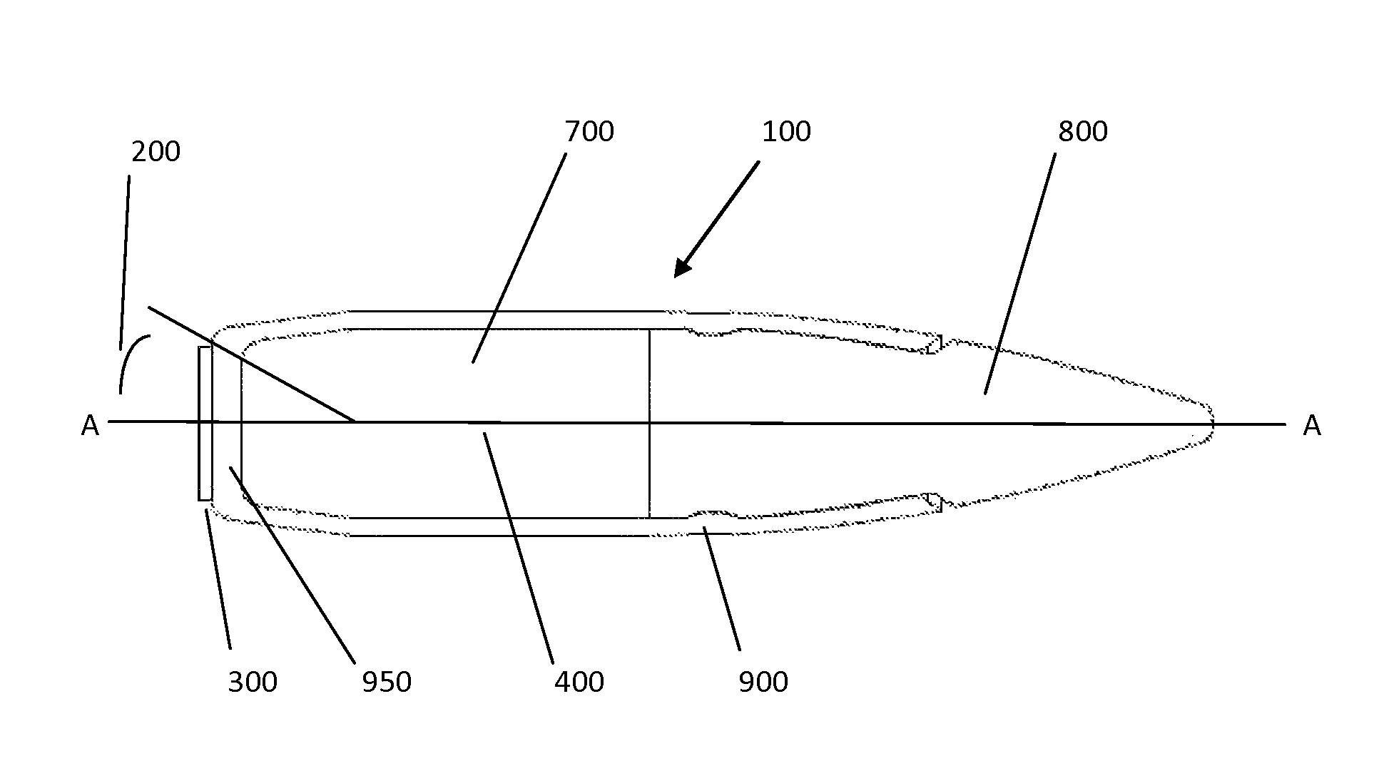
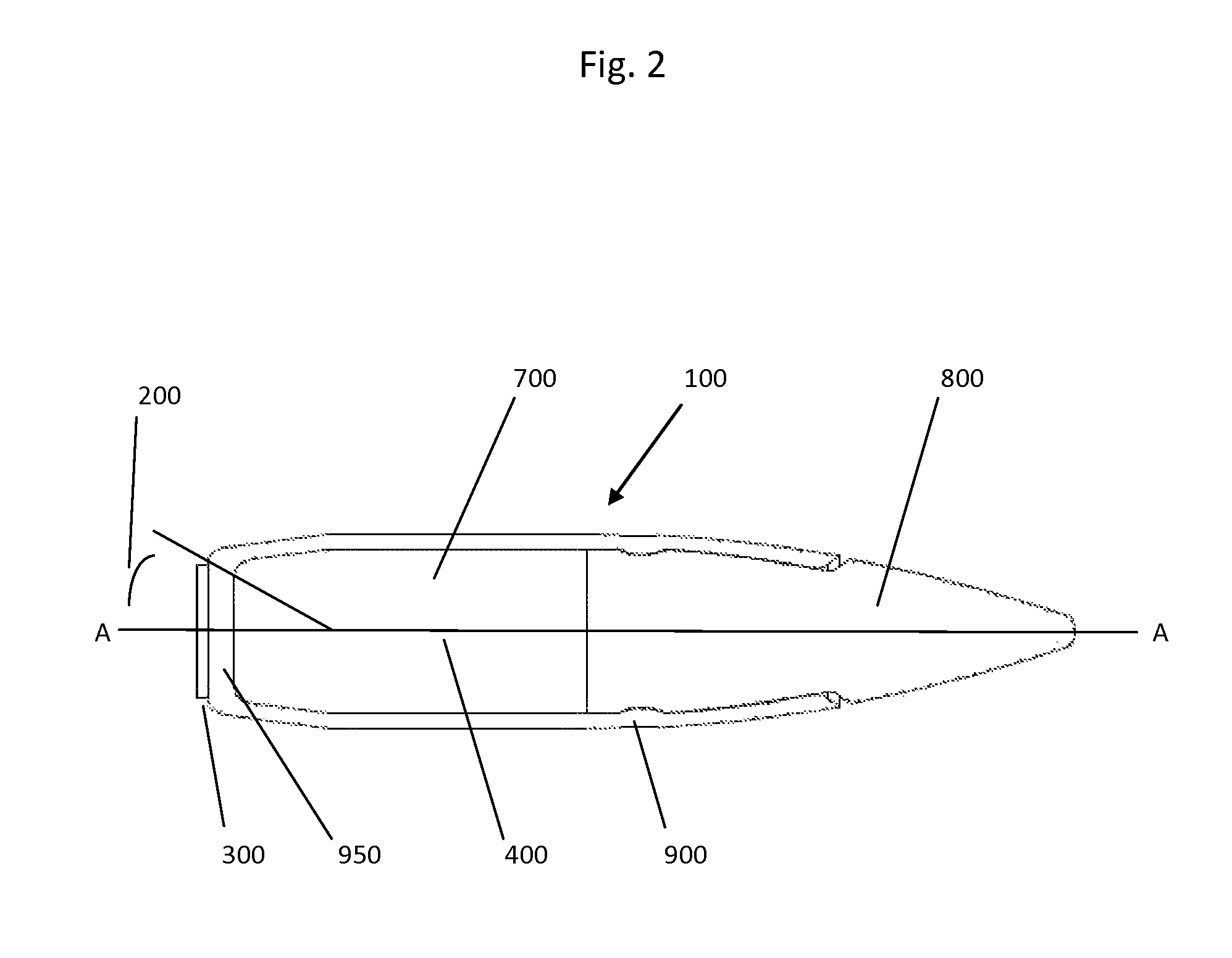
[0014]The present invention addresses the above detailed problems and failings in the prior art, by providing a method for manufacturing an enhanced, functional, low observable photoluminescent tracer round/projectile, useful for small arms, i.e. small caliber applications including pistols, rifles, and machine guns—wherein the tracer is visible only at an angle of from 0 to about 20 degrees from the rear of the projectile, under low light or night conditions using a night vision device, at a distance of at least 400 meters. The subject low observable tracer projectile is formed of a combination of a sprinkling, i.e. a plurality of small retro-reflective glass beads, or cat's eye retro-reflectors, or corner cube retro-reflectors, coated on the surface of novel photoluminescent tracer material, which material can be either (1) a first phosphor base material of about 0 to about 50 wt. % Ca, about 0 to about 50 wt. % Sr, and about at least 50 wt. % S, with a combination of minor dopant ingredients selected from the group of Eu, Sm, Dy, Ce, Mn, Cu, Al, and Tm (h

Problems solved by technology

Historically, gunners relied on observing the impact of their bullets (i.e. projectiles) in order to adjust their aim—which is not effective, as often the impact point is not visible.
A disadvantage of such brightly burning pyrotechnic is that the enemy can easily trace back the stream of tracer ammunition to disclose the gunner's position.
To help remediate this problem, subdued tracers have a built in delay—which causes them to burn brightly after at least 100 yards—such that it isn't easy to establish the position of the gunner.
But, such a delay is only partially effective—so, dim tracers were introduced, wherein the tracer can only be viewed with the aid of night vision equipment—allowing the gunner to better observe his fire and “walk” it to the desired location in low light or night conditions.
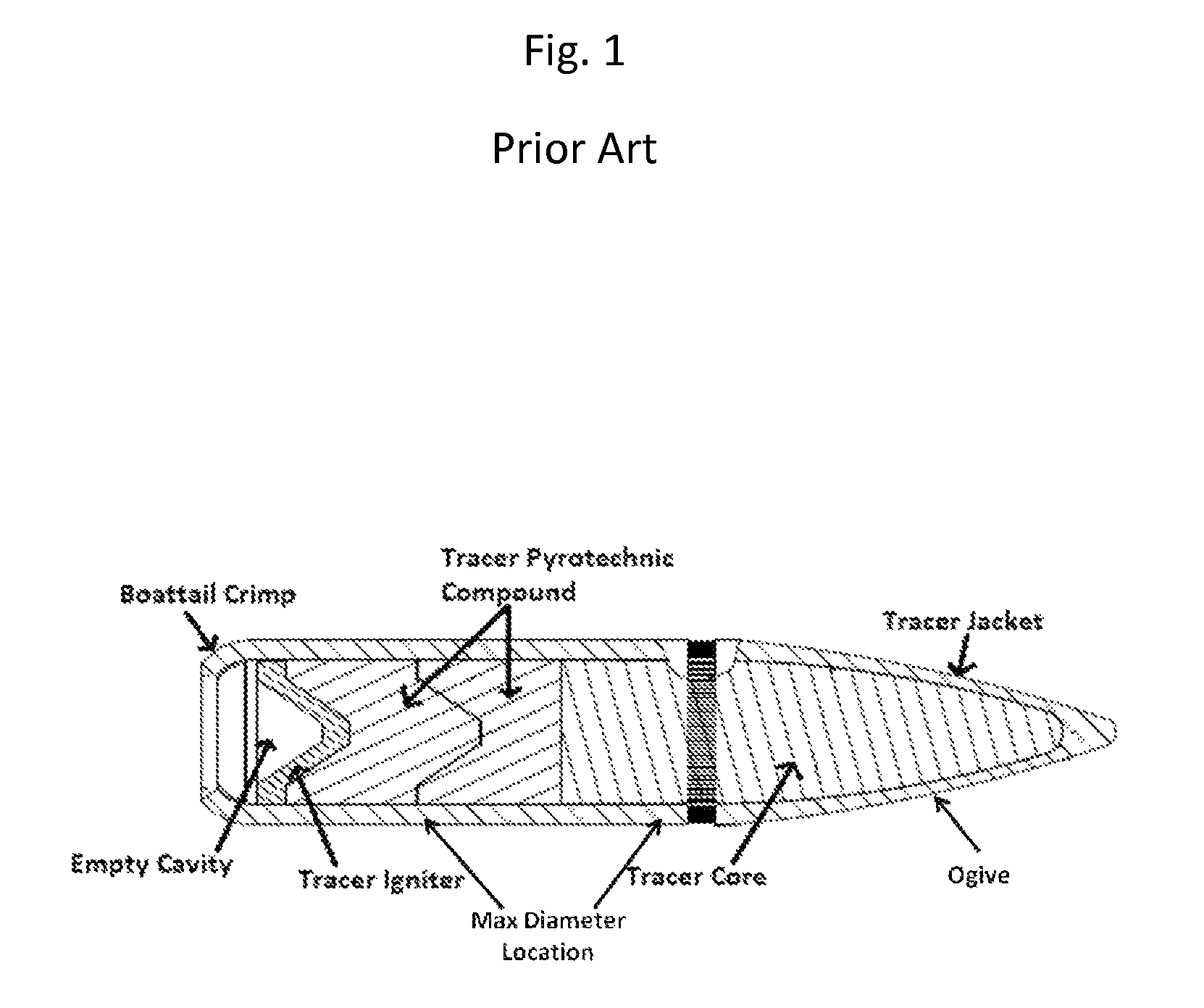
These shortcomings include—(1) the exothermic incendiary nature of energetic tracer materials makes them a fire hazard—especially in wooded or grass covered training areas—and can present significant undesirable consequence in battle; (2) the tracers lose mass in flight as the pyrotechnic reaction progresses, creating an inherent inaccuracy and lack of precision; (3) the particular pyrotechnic materials used for energetic tracers create environmental and hazardous material problems; (4) the energetic tracer, using incendiary fuels and oxidizers are difficult to manufacture; and, finally, (5) pyrotechnic energetic tracers are bi-directional, i.e. meaning they can be seen by the shooter as well as the enemy.
Unfortunately, energetic tracers can never be a totally reliable

Method used


Image

  • Non-pyrotechnic, low observable tracer
  • Non-pyrotechnic, low observable tracer
  • Non-pyrotechnic, low observable tracer

Examples


examples

[0033]As an example of a preferred embodiment of the present invention, the Ca / Sr / S phosphor material useful in the present invention can be prepared in a typical reaction, using chemicals which were reagent grade, purchased from Sigma-Aldrich Corporation, without any further purification; wherein for example: 10 g CaCO3, 10 g S, 0.05 g KCl, and 0.05 g NaCl, are mixed with the corresponding amounts of the dopant ingredients—such as the rare earth chlorides (EuCl3, SmCl3, DyCl3CeCl3) and / or transition metal chlorides (MnCl2, CuCl2 and AlCl3) and placed in a ball mill (Retsch, PM 100) at 300 RPM for four hours. The resulting mixture was then fired in a furnace (Thermo Scientific, ED 1545M) for two hours at 1200° C. in an oxygen free zone. To achieve an oxygen free environment the double crucible method is implemented. The inner crucible contains the mixture and the outer one is filled with graphite to scavenge oxygen.

[0034]As a second example of another preferred embodiment of the pre...


PUM


Abstract

A method of manufacturing a low observable photoluminescent tracer projectile, for use with a small caliber weapon at night—which method utilizes a base phosphor material of Ca, Sr and S, or a base phosphor material of Y2, O2, and S—with a combination of minor dopant ingredients; which base phosphor material is mixed with a clear binder to form a photoluminescent material which is applied to the rear end, or base, of a small arms projectile as a thin layer; to which thin layer is added a layer of small retro-reflectors—whereby, when this projectile is fired from the weapon, the photoluminescent mixture will be activated and will be observable, using night vision at an angle of 0 to about 20 degrees from the rear end of the projectile.

Description

FEDERAL RESEARCH STATEMENT[0001]The inventions described herein may be manufactured, used and licensed by, or for the U.S. Government, for U.S. Government purposes.BACKGROUND OF INVENTION[0002]1. Field of the Invention[0003]The present invention relates to luminescent material for use as military tracer rounds and more particularly, to such materials whose photoluminescence is excited by the energy emitted by military propellants and are thereby observable at night, with the aid of conventional night vision devices.[0004]2. Related Art[0005]Historically, gunners relied on observing the impact of their bullets (i.e. projectiles) in order to adjust their aim—which is not effective, as often the impact point is not visible. As a solution to this problem, in about 1915 tracer ammunition (also referred to as pyrotechnic tracer, standard tracer, standard pyrotechnic tracer, and / or M62 Tracer) was introduced—ammunition containing a pyrotechnic composition that burned very brightly—making t...

Claims


Application Information

Patent Timeline
IPC IPC(8): F42B33/02F42B12/38
CPCF42B33/02F42B12/387F42B12/38
Inventor HORCH, MATTHEW T.KELLY, CHRISTEL M.GLASPELL, GARRY P.
Owner UNITED STATES OF AMERICA THE AS REPRESENTED BY THE SEC OF THE ARMY
Why Eureka
Try Eureka