Directional MEMS microphone and receiver device

a directional mems and receiver technology, applied in the field of microphone technology, can solve the problems of small sensitivity difference, high risk of howling, and sound pressure difference acting on the diaphragm b>11/b>, and achieve the effect of improving the directivity performance of the conventional directional mems microphon

Active Publication Date: 2016-06-28
SHANDONG GETTOP ACOUSTIC
View PDF13 Cites 11 Cited by
  • Summary
  • Abstract
  • Description
  • Claims
  • Application Information

AI Technical Summary

Benefits of technology

[0009]An object of the invention is to provide such a directional MEMS microphone comprising a tuning cavity which can remarkably improve the directivity performance of the conventional directional MEMS microphone.
[0022]Compared with the prior art, one of the above technical schemes has the following advantages.
[0023]As a result of microphone size restriction in the prior art, the back volume formed on the bottom of the MEMS microphone and the back cavity formed between the cover and the PCB are small, so the channels of the two acoustic ports can't be designed long enough, which leads to the sound pressure difference acting on the diaphragm 11 is minor, thereby the sensitivity difference being minor as well. Thus, sounds from various directions can all enter the inside of the MEMS microphone, and the background noise can't be eliminated by means of sensitivity difference. Since the sensitivity difference depends on the sound pressures acting on the diaphragm from the two directions, the increase of the sensitivity difference is gained by increasing the sound pressure difference acting on the diaphragm of the directional MEMS microphone from the two directions. Thus, the embodiments of the present invention provide a directional MEMS microphone wherein the housing is connected to the outside world through the internal acoustic ports, the tuning cavity and the external acoustic ports in turn. The tuning cavity is a volume which has different dimensional shapes. The transmission distance of sound entering the inside of the microphone via different external acoustic ports is changed by setting various volumes of tuning cavities, thereby a larger sensitivity difference can be achieved by increasing the sound pressures acting on the diaphragm. Therefore, the background noise from a certain angle can be eliminated and the directivity of the directional MEMS microphone can be improved.

Problems solved by technology

If the directional angle of a microphone is larger, the pickup range is wider but it also has a higher risk of howling caused by picking sounds from loudspeaker field.
As a result of size restriction, the back volume formed on the bottom of the MEMS microphone and the back cavity formed between the cover and the PCB are small, so the channels of the two acoustic ports can't be designed long enough, which leads to the sound pressure difference acting on the diaphragm 11 is minor, thereby the sensitivity difference being minor as well.

Method used


Image

  • Directional MEMS microphone and receiver device
  • Directional MEMS microphone and receiver device
  • Directional MEMS microphone and receiver device

Examples


first embodiment

[0041]A first embodiment provides a directional MEMS microphone which comprises a microphone cover, a printed circuit board (PCB), a application specific integrated circuit (ASIC), a MEMS die, a diaphragm, a damping, a metal wire (s), at least two internal acoustic ports and external acoustic ports corresponding to the internal acoustic ports. The microphone cover is coupled to the PCB to form a housing. The ASIC chip and the MEMS die are attached to the PCB within the housing. The diaphragm is attached to the MEMS die. The ASIC chip, the MEMS die and the PCB are electrically interconnected by the metal wire (s). The damping is secured to cover either one of the internal acoustic ports or one of the external acoustic ports corresponding to the internal acoustic ports. The internal acoustic ports include a first internal acoustic port which is disposed on the PCB within the housing and is corresponded to the position of the diaphragm and a second internal acoustic port which is dispo...

second embodiment

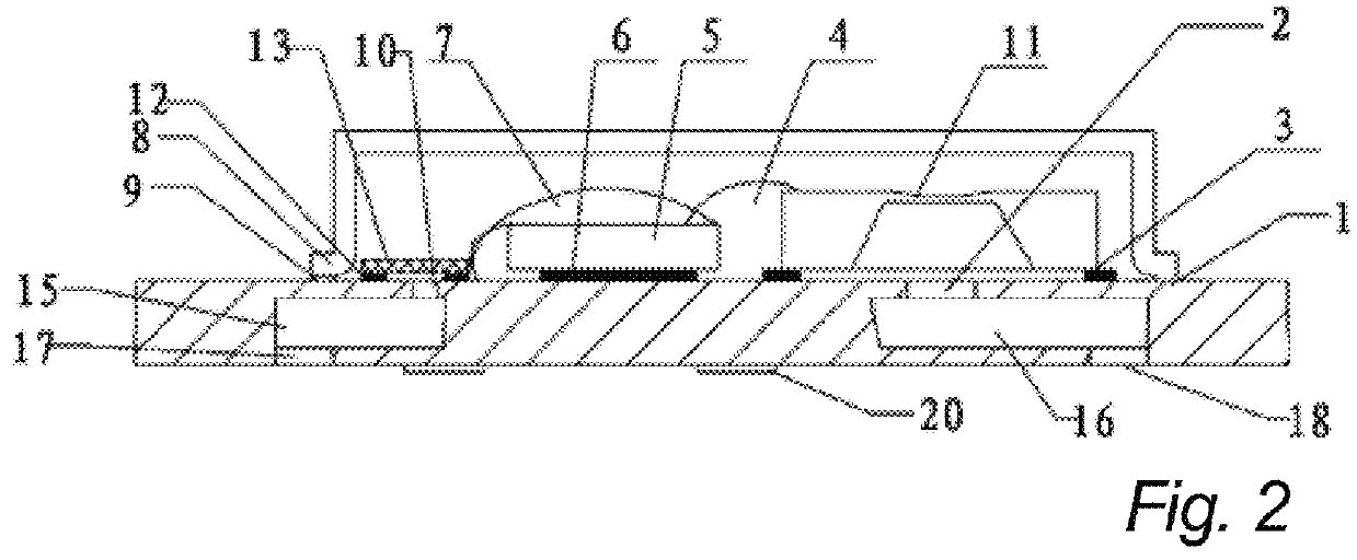
[0049]In the present invention, taking the sound transmission channels formed respectively by two groups of internal acoustic ports, tuning cavities and external acoustic ports as an example, the directional MEMS microphone provided by the present invention is depicted. Referring to FIG. 2, the directional MEMS microphone comprises a PCB 1, a internal acoustic port 2, a metal wire (s) 4, an ASIC chip 5, a microphone cover 8, a internal acoustic 10, a MEMS die 11, a diaphragm and damping 13, a tuning cavity 15, a tuning cavity 16, a external acoustic port 17, and a external acoustic port 18.

[0050]A housing is formed by connecting the microphone cover 8 and the PCB 1. More particularly, the microphone cover 8 and the PCB 1 are secured together by the cover bonding adhesive 9, solder paste, or other bonding materials. The ASIC chip 5 and the MEMS die 11 are attached on the PCB 1 within the housing. More particularly, the ASIC chip 5 is attached to the PCB 1 by the ASIC bonding adhesive...

fourth embodiment

[0067]a directional MEMS microphone of the present invention is illustrated in FIG. 6. In the directional MEMS microphone provided by the embodiment, the tuning element 14 includes a wire board 14a, a body 14b and a tuning cover 14d. The body 14b is attached to the PCB 1 outside the housing via the wire board 14a by a adhesive 14c disposed between the body 14b and the wire board 14a, and a protective volume which holds the microphone cover 8 and the PCB 1 is formed by connecting the wire board 14a and the tuning cover 14d. The tuning cavity 16 is disposed inside the body 14b and the external acoustic port 18 is disposed on the body 14b. The tuning cavity 15 is disposed inside the tuning cover 14d and the external acoustic port 17 is disposed on the tuning cover 14d. The internal acoustic port 10 is disposed on the microphone cover 8. The protective volume which holds the microphone cover 8 and the PCB 1 is formed for shielding the directional MEMS microphone by connecting the wire b...


PUM


Abstract

The present invention provides a directional MEMS microphone and a receiver device wherein MEMS microphone comprises a microphone cover, a printed circuit board (PCB), a application specific integrated circuit (ASIC) chip, a MEMS die, a diaphragm, a damping, a metal wire(s), at least two internal acoustic ports and at least two external acoustic ports corresponding to the internal acoustic ports. The microphone further comprises a tuning cavity which includes a first tuning cavity by which a first internal acoustic port is communicated with a first external acoustic port, or by which a second internal acoustic port is communicated with a second external acoustic port. Compared with the prior art, the directional MEMS microphone including the tuning cavity to form a sound transmission channel by connecting the internal acoustic port and the external acoustic port expands the sound transmission distance, thereby increasing the sensitivity the directivity of the MEMS microphone.

Description

CROSS-REFERENCE TO RELATED APPLICATIONS[0001]This application is related to and claims the benefit of Chinese Patent Application No. 201310718505.7 filed on Dec. 23, 2013, the entire contents of which are herein incorporated by reference.FIELD OF THE INVENTION[0002]This invention relates generally to a microphone technology field. More particularly, this invention relates to a directional MEMS microphone and a receiver device.BACKGROUND OF THE INVENTION[0003]The MEMS microphone, also called MEMS transducer, refers to a microphone fabricated with Microelectromechanical System technology.[0004]The microphone contains two chips, a MEMS die and an Application Specific Integrated Circuit (ASIC) chip which are packaged into a surface mountable package. The MEMS die contains a rigid perforated back electrode and an elastic silicon diaphragm serving as a capacitor which can transform the sound wave into the capacitance changes. The ASIC chip is used to detect the capacitance changes and out...

Claims


Application Information

Patent Timeline
Patent Type & Authority Patents(United States)
IPC IPC(8): H04R1/20H04R1/02H04R1/34H04R1/28
CPCH04R1/342H04R1/02H04R1/2823H04R2201/003H04R2201/02H01L2224/48137H01L2924/16151H01L2924/16152
Inventor JINGMING, WAN
Owner SHANDONG GETTOP ACOUSTIC
Why Eureka
Try Eureka