Multiple probe actuation

a multi-probe technology, applied in the field of multi-probe actuation, can solve the problems of inflexible design, complex and corresponding cost of sensors, and redesign of layou

Active Publication Date: 2016-07-12
INFINITESIMA
View PDF9 Cites 4 Cited by
  • Summary
  • Abstract
  • Description
  • Claims
  • Application Information

AI Technical Summary

Benefits of technology

[0013]As well as delivering different amounts of energy to different probes during a single scan sequence, different amounts of energy are typically also delivered to at least one of the probes by the actuation beam during two or more scan sequences. This enables the position of a single probe to be changed from time to time independently of the other probes.

Problems solved by technology

Parallel operation in scanning probe microscopy (SPM) is a challenge because multiple probe detection must be implemented as well as independent actuation systems for each cantilever.
A major difficulty with such integrated systems is the complexity and corresponding cost of the sensors.
The designs are also inflexible since changing a simple parameter such as the pitch or spring constant of the cantilevers also requires a redesign of the layout and costly fabrication.
As a result, parallel SPM systems of this sort have not been widely used.
However, such piezo-elements often have a limited speed of response due to their size and mechanical characteristics.
Smaller elements which can be integrated into the cantilever can be employed for fast scanning applications but the required fabrication and electrical connection is a challenge.
However this approach has not been used for multiple probe control due to the increased number of optical components needed for alignment and focusing.

Method used


Image

  • Multiple probe actuation
  • Multiple probe actuation
  • Multiple probe actuation

Examples


Embodiment Construction

)

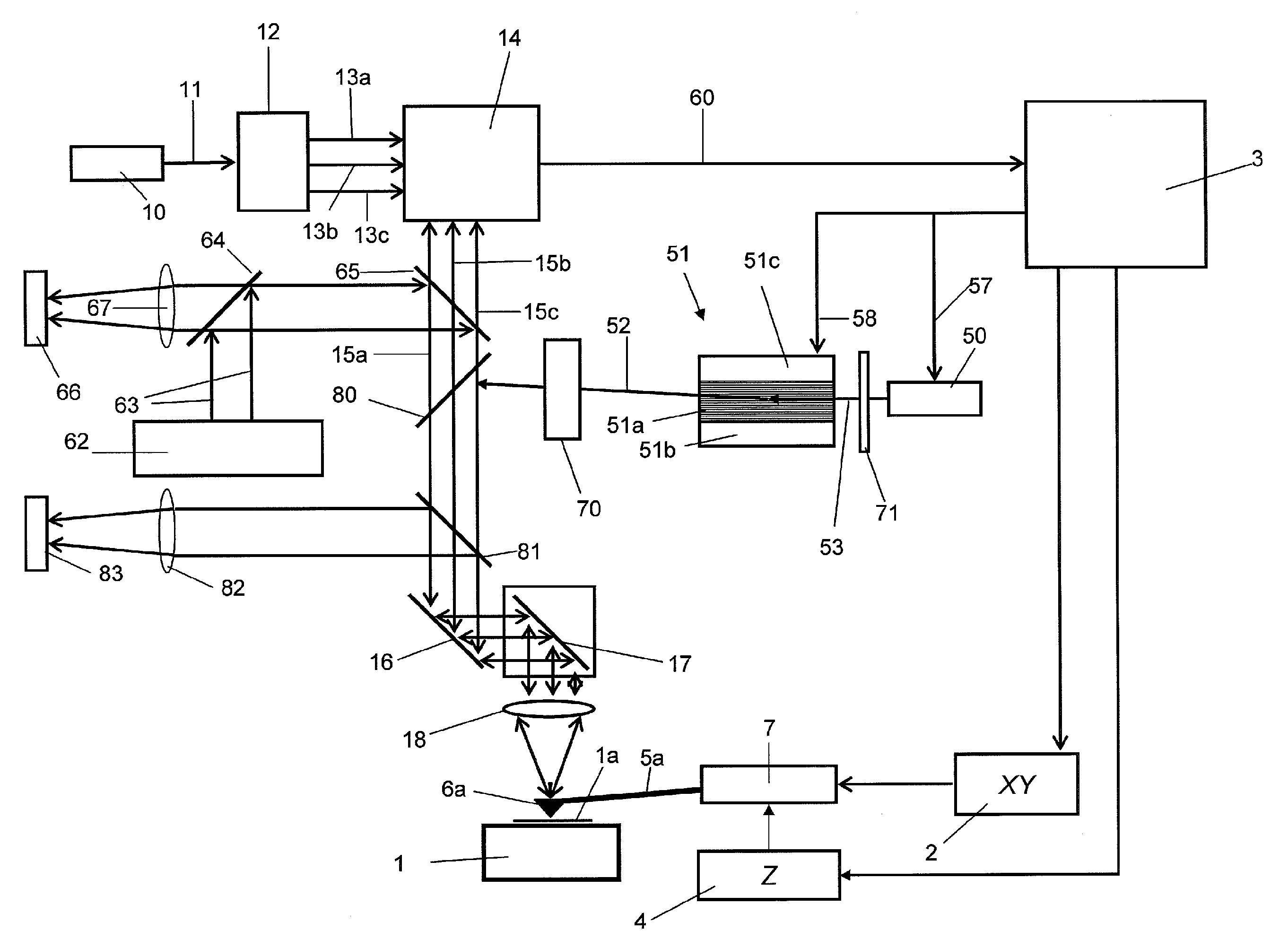
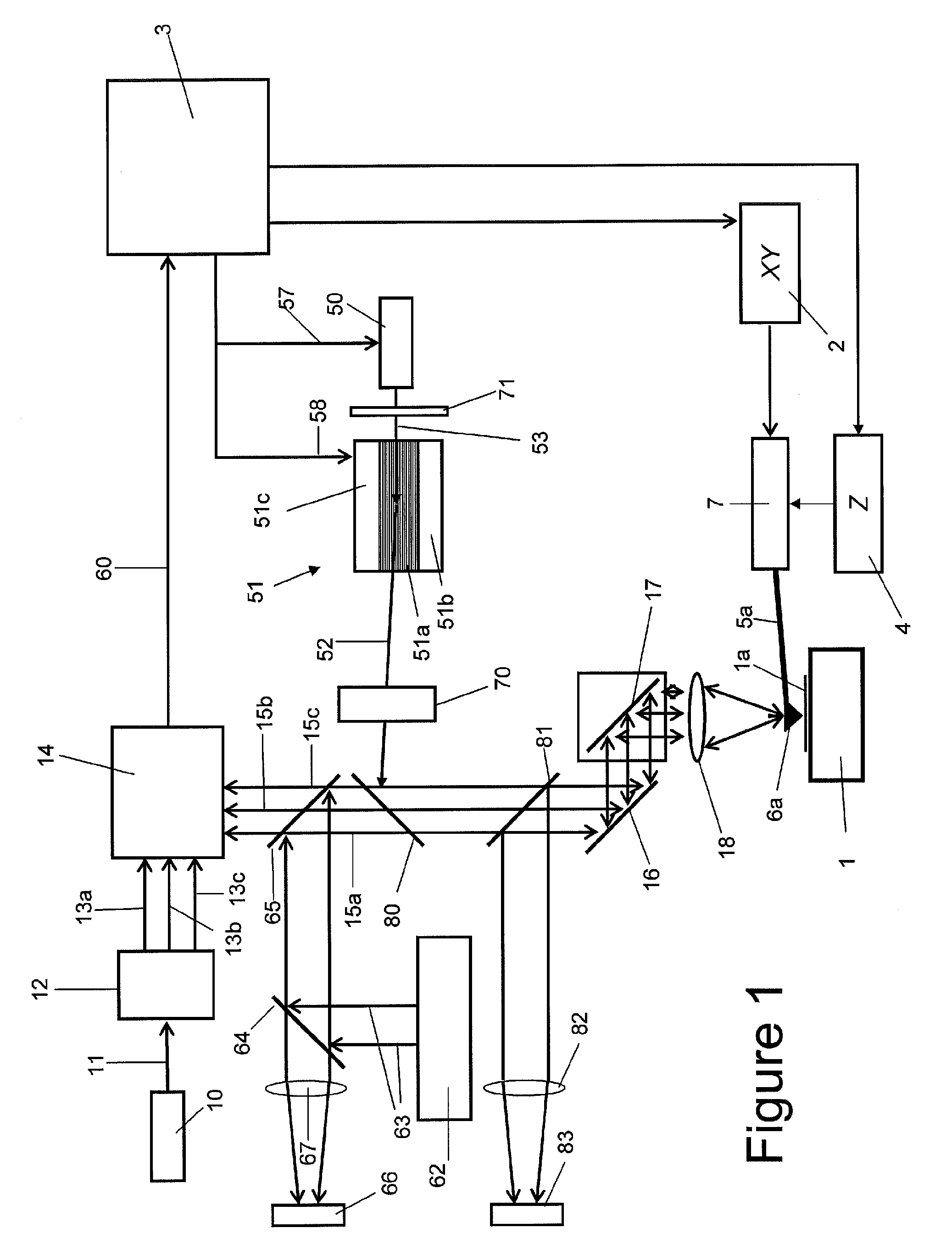
[0031]With reference to FIG. 1, a scanning probe microscope that incorporates an interferometer based sensing system and photothermal actuation system in accordance with the present invention is shown. The microscope comprises a moveable stage 1 adapted to receive a sample 1a whose surface is to be investigated by an array of thermal actuated bimorph probes, only one of which is shown in FIG. 1. The scanning capability is provided by two conventional drive systems: an x,y scanner 2 operable by an SPM controller 3 to provide relative motion of the probe array in the plane (x, y) of the sample 1a; and a z positioning system comprising piezoelectric drivers 4 operable to move the probe and sample towards and away from each other (z direction) over ranges larger than that achievable by the photothermal actuation of the probe array.

[0032]The probe array comprises a linear array of cantilever beams 5a, each carrying a tip 6a which tapers to a point, and which is located towards a distal ...


PUM

PropertyMeasurementUnit
thickaaaaaaaaaa
thickaaaaaaaaaa
refractive indexaaaaaaaaaa

Abstract

A method of actuating a plurality of probes. Each probe may be made of two or more materials with different thermal expansion coefficients which are arranged such that when the probe is illuminated by an actuation beam it deforms to move the probe relative to a sample. Energy is delivered to the probes by sequentially illuminating them with an actuation beam via an objective lens in a series of scan sequences. Two or more of the probes are illuminated by the actuation beam in each scan sequence and the actuation beam enters the objective lens at a different angle to an optical axis of the objective lens for each probe which is illuminated in a scan sequence. The actuation beam is controlled so that different amounts of energy are delivered to at least two of the probes by the actuation beam during at least one of the scan sequences.

Description

FIELD OF THE INVENTION[0001]The present invention relates to a method of actuating a plurality of probes, and apparatus operable to perform such a method.BACKGROUND OF THE INVENTION[0002]The speed of scanning in a probe microscope can be increased by operating two or more cantilevers in parallel, such that data is acquired simultaneously from each probe. Parallel operation in scanning probe microscopy (SPM) is a challenge because multiple probe detection must be implemented as well as independent actuation systems for each cantilever. As a result, parallel SPM systems have in the past differed significantly from conventional SPM systems. For example, some systems have deployed cantilevers with integrated piezo-resistive sensors, and integrated zinc oxide Z-actuators (Quate et al Applied Physics Letters vol 67 No 26 3918 (1995)). A major difficulty with such integrated systems is the complexity and corresponding cost of the sensors. The designs are also inflexible since changing a si...

Claims


Application Information

Patent Timeline
Patent Type & Authority Patents(United States)
IPC IPC(8): G01Q10/00G01Q20/02G11B9/14G11B11/00G01Q70/06G01Q10/04G03F7/20
CPCG01Q10/00G01Q10/045G01Q20/02G01Q70/06G11B9/1409G11B11/002G01N2291/0256G01N2291/106G03F7/2002G03F7/2049G11B9/1445G03F1/24G03F1/84
Inventor HUMPHRIS, ANDREW
Owner INFINITESIMA
Why Eureka
Try Eureka