Methods and receiver for positioning of clock related spurious signals

Active Publication Date: 2016-07-12
TELEFON AB LM ERICSSON (PUBL)
View PDF31 Cites 2 Cited by
  • Summary
  • Abstract
  • Description
  • Claims
  • Application Information

AI Technical Summary

Benefits of technology

[0019]According to a second aspect of the present invention, a receiver for positioning a spurious signal for reducing the impact of the spurious signal on a received OFDM signal by down-converting said OFDM signal to base band, is disclosed. The receiver comprises a down-converting mixer configured to determine the frequency of the spurious signal based on a frequency of a first oscillator, and to determine the frequency for the respective sub-carrier of the OFDM signal and determining the difference between the frequency of a sub-carrier and a spurious signal. The receiver also comprises a controller operatively

Problems solved by technology

The smaller the mobile terminal or a transceiver unit is, the larger is the risk for internally generated interference.
One typical example of internally generated interference is the interference caused by a clock signal leaking into the Radio Frequency (RF) parts of the transceiver unit.
The harmonics of the clock signal extend into the RF domain and might therefore interfere with the received signal.
This is especially a problem at low power levels of the received signal.
However, based on practical experience such signal

Method used


Image

  • Methods and receiver for positioning of clock related spurious signals
  • Methods and receiver for positioning of clock related spurious signals
  • Methods and receiver for positioning of clock related spurious signals

Examples


first embodiment

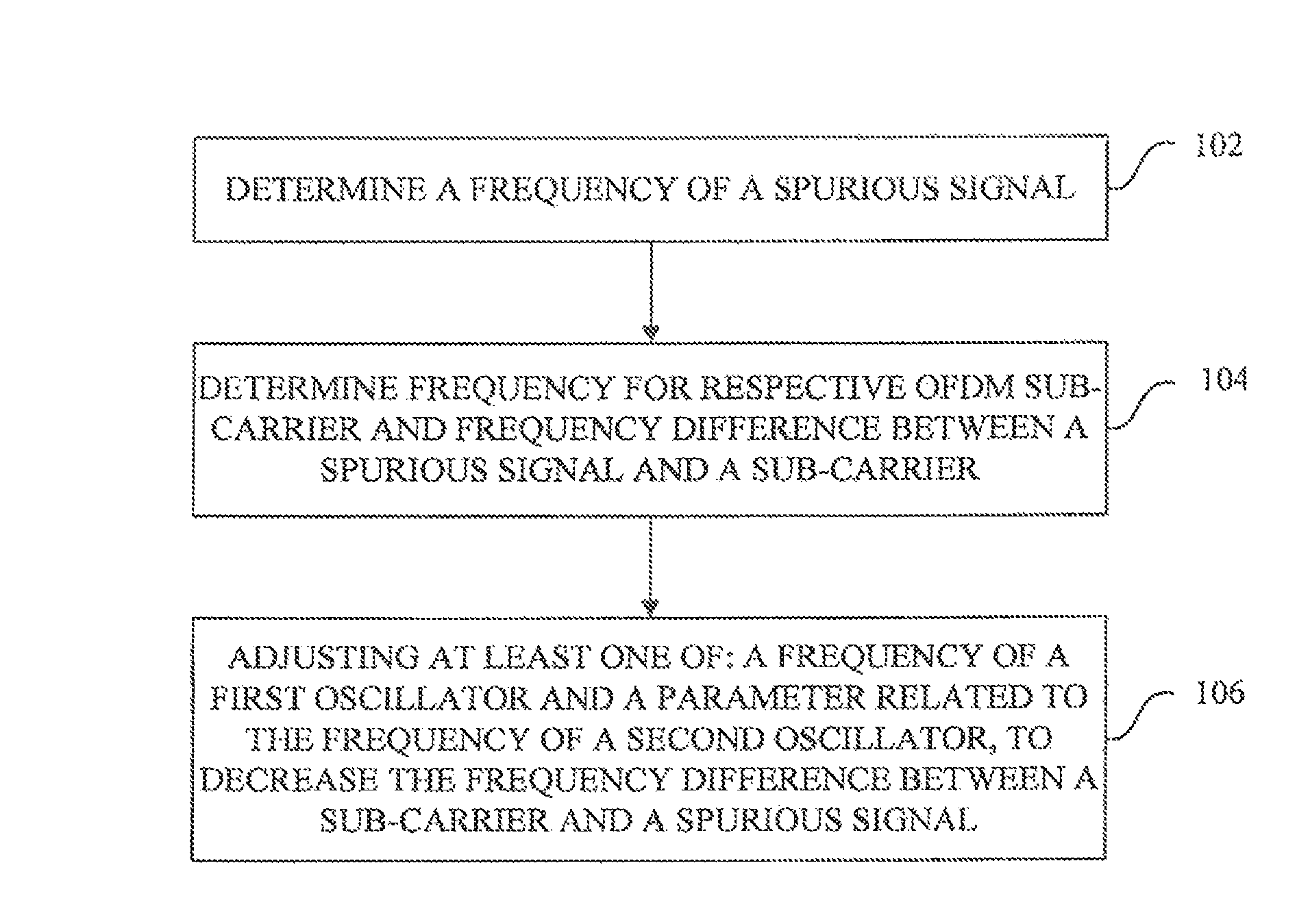
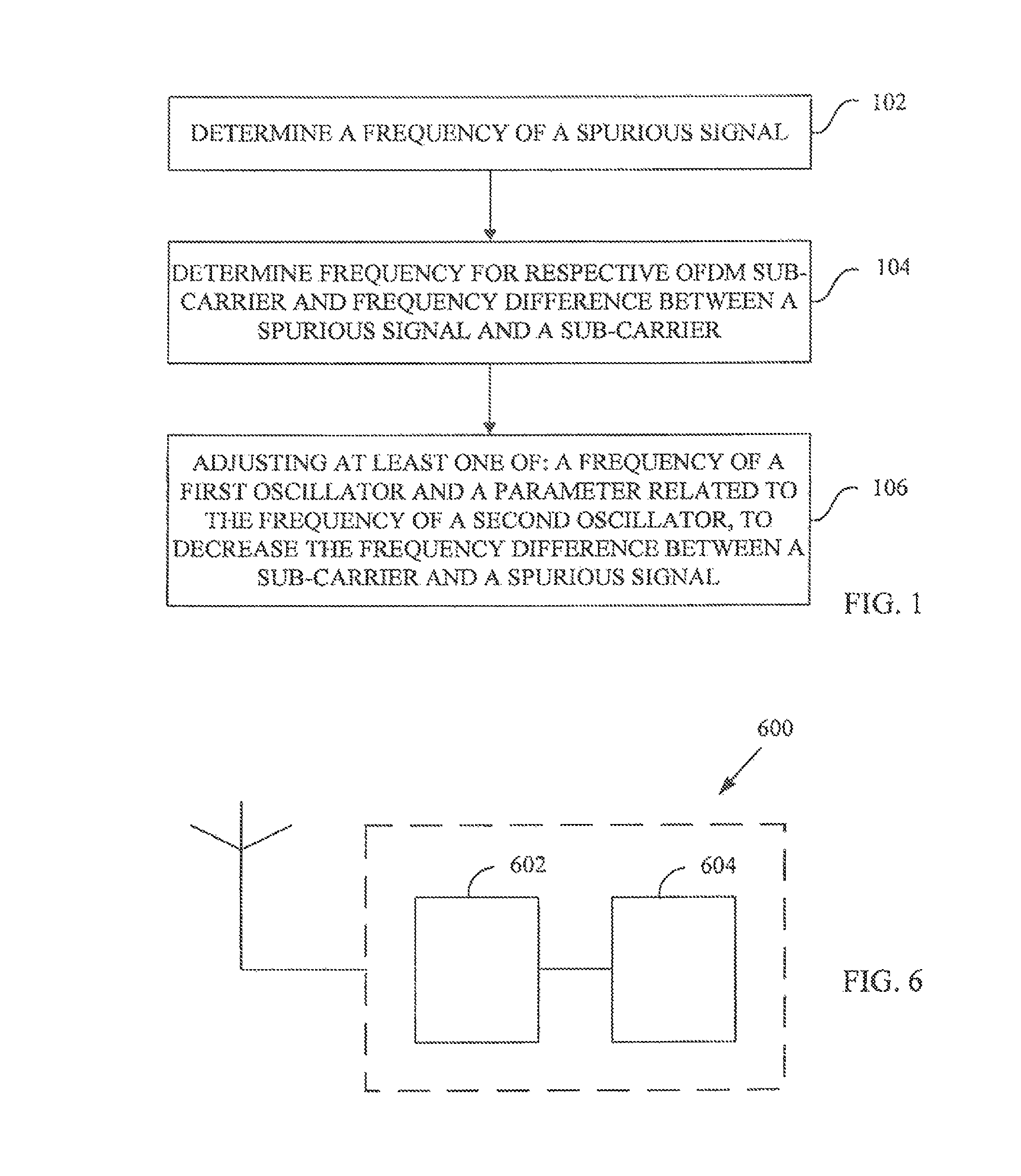
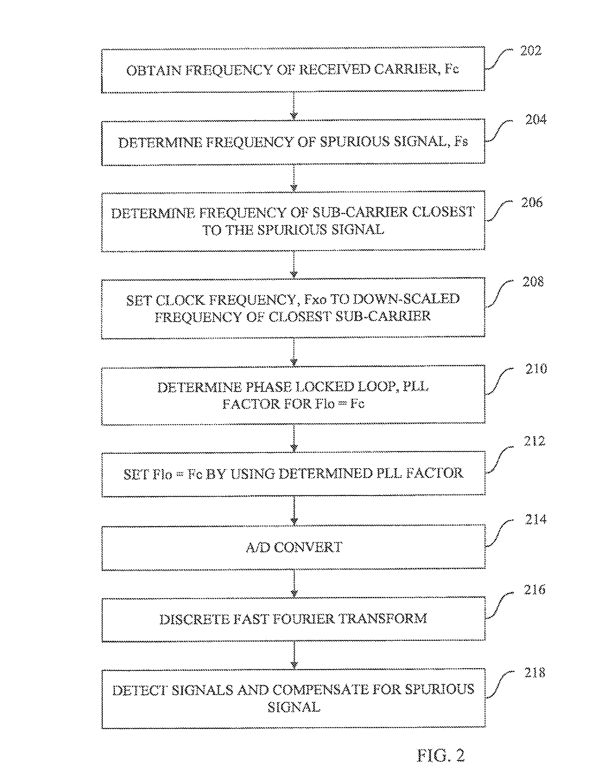
[0034]Within a first embodiment, adaptation of the frequency of both the internally generated clock signal as well a parameter in the Phase Locked Loop, PLL transforming the frequency of a clock signal to a Local Oscillator, LO carrier frequency, is performed. In this embodiment, the spurious signal originating from the clock signal is translated to a frequency corresponding to a sub-carrier frequency.

second embodiment

[0035]Within the present invention, adaptation is performed of either an internally generated clock signal or the LO carrier frequency by at maximum half the sub-carrier spacing at radio frequency and a digital frequency compensator that is introduced to compensate for a LO offset.

[0036]Within the two mentioned embodiments suppression of spurious signals is performed in a subsequent base band processing, for instance, by either setting soft values on the affected sub-carrier to zero (so called nulling), or by estimation and subsequent subtraction of spurious signals. It shall be mentioned that suppression is not limited by the two mentioned methods. Rather other methods may just as well be applied.

[0037]It can also be mentioned that a signal having a frequency F is distributed over different frequency bins, when transformed by a Fast Fourier Transform, FFT of a certain dimension. The closer F is to a certain carrier frequency, the fewer sub-carriers are affected.

[0038]Thus, performa...


PUM


Abstract

Methods and a receiver of positioning a spurious signal for reducing the impact of the spurious signal on a received Orthogonal Frequency Division Multiplexing, OFDM signal, are presented. The method comprises determining the frequency of a spurious signal (steps 102, 204, 404), determining the frequency for the respective sub-carrier of the OFDM signal and the difference between the frequency of a sub-carrier and the frequency of a spurious signal (steps 104, 206, 406), and adjusting at least one of: the frequency of the first oscillator (step 208) and a parameter related to the frequency of a second oscillator, to decrease the frequency difference between a sub-carrier and a spurious signal (steps 106, 212, 408). By positioning a spurious signal at or near a sub-carrier frequency, the performance impact of the spurious signal is reduced, and the receiver performance improved.

Description

TECHNICAL FIELD[0001]This invention pertains in general to the field of suppression of clock spurious signals. More particularly the invention relates to methods and a receiver for positioning of clock spurious signals for decreasing the negative effect of said spurious signals on an Orthogonal Frequency Division Multiplexing (OFDM) signal received by a receiver.BACKGROUND[0002]Interference in a mobile terminal can be created by internal components or units. The smaller the mobile terminal or a transceiver unit is, the larger is the risk for internally generated interference. One typical example of internally generated interference is the interference caused by a clock signal leaking into the Radio Frequency (RF) parts of the transceiver unit. The harmonics of the clock signal extend into the RF domain and might therefore interfere with the received signal. This is especially a problem at low power levels of the received signal.[0003]Sensitivity is a key parameter for receivers due ...

Claims


Application Information

Patent Timeline
IPC IPC(8): H04K1/10H04L27/26H04B15/06H04L27/00
CPCH04L27/2649H04B15/06H04L27/2657H04L2027/0016H04L2027/0032H04L2027/0065
Inventor LINDOFF, BENGTSUNDSTROM, LARSWILHELMSSON, LEIF
Owner TELEFON AB LM ERICSSON (PUBL)
Why Eureka
Try Eureka