Neutralization and containment of redox species produced by circumferential electrodes

a technology of redox species and electrodes, applied in the field of electrochemical arrays, can solve the problems of undesirable extra synthesis, labile groups, and insufficient understanding of crosstalk, so as to prevent bleeding over of ph changes, reduce the distance between electrodes, and reduce the chance of crosstalk or ph bleed

Active Publication Date: 2016-07-19
CUSTOM ARRAY
View PDF48 Cites 12 Cited by
  • Summary
  • Abstract
  • Description
  • Claims
  • Application Information

AI Technical Summary

Problems solved by technology

Additionally, some protecting groups are labile to only specific types of reagents.
Crosstalk refers to the bleed-over of reagents generated at one electrode to another nearby electrode causing undesirable extra synthesis at that nearby electrode.
However, in organic-based deblock solutions, the mechanism of preventing crosstalk is not necessarily well understood but may involve molecular interactions that remove or pacify acidic reagent by some other species.
However, the Montgomery system encounters problems when the distance between electrodes is decreased (or the density of electrodes per unit area of an electrode array is increased.

Method used


Image

  • Neutralization and containment of redox species produced by circumferential electrodes
  • Neutralization and containment of redox species produced by circumferential electrodes
  • Neutralization and containment of redox species produced by circumferential electrodes

Examples


example 1

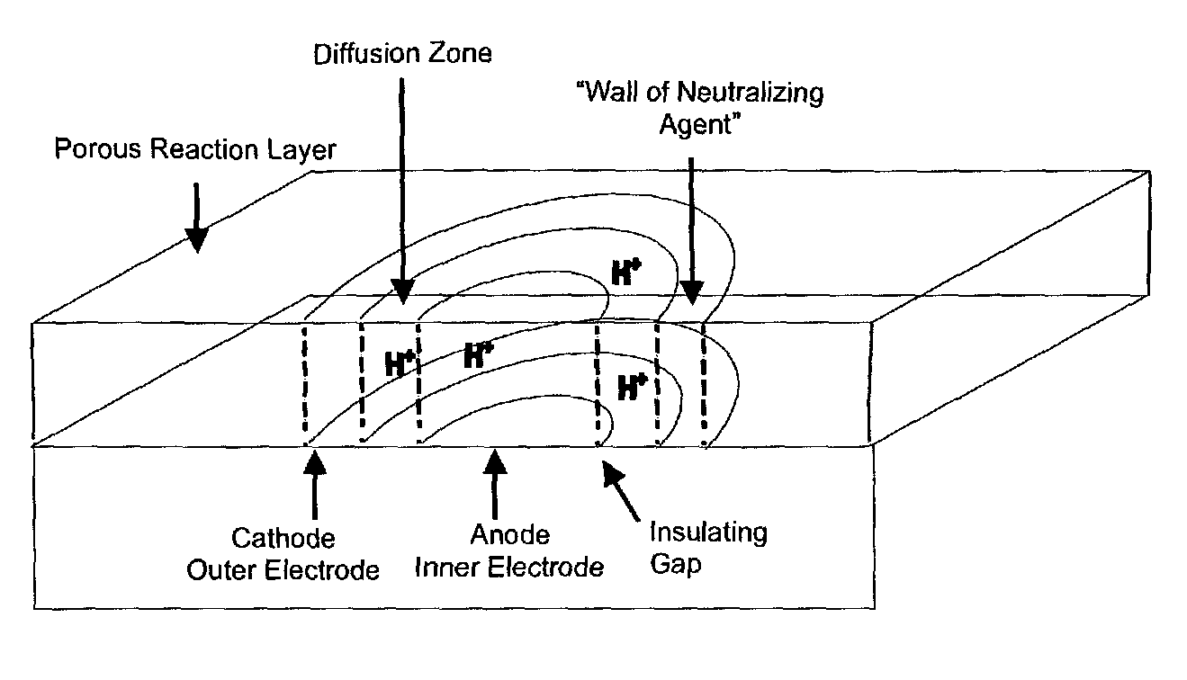
[0065]This example provides a chemical description of an electrochemical buffer formulation using an electrode array having a plurality of discontinuous circumferential electrodes. The central electrode producing protons (i.e., anode) is surrounded by a discontinuous set of electrodes (i.e., acting as cathodes) that help neutralize the protons, which are produced and diffuse away from the anode (active electrode) as shown in FIG. 8. In FIG. 8, the active electrode marked “A” represents the anode. The surrounding electrodes marked “C” are the cathodes. The active electrode can be turned “on” (i.e., generate current flow or voltage) to generate acid, while the surrounding electrodes can also be “turned on” (opposite voltage or current flow) to produce base. The discontinuous circumferential ring of electrodes (cathodes or counter electrodes in this example) also represents a form of circumferential electrodes, but they are not attached to each other (i.e., are discontinuous). However,...

example 2

[0067]This example illustrates different confinement techniques for electrochemical synthesis of oligonucleotides. We synthesized approximately 1,000 sequences of different 35-mer oligonucleotides on two separate CUSTOMARRAY™ oligonucleotide microarray devices each having over 12,000 electrode sites with a distance between the outer edges of circular electrodes of approximately 33 microns. For the control oligonucleotide microarray, we synthesized oligonucleotide probes electrochemically using the method disclosed in the Montgomery patents having a buffered deblocking solution to try to confine the acid generated at the active (anode) electrodes. This technique further utilized an off chip Pt electrode as a common counter electrode. In addition, four-fold extra systemic base was added to the deblocking solution for the control oligonucleotide array as compared with the inventive oligonucleotide array using a discontinuous circumferential electrode pattern. The pattern of oligonucleo...


PUM

PropertyMeasurementUnit
average distanceaaaaaaaaaa
distanceaaaaaaaaaa
diameteraaaaaaaaaa

Abstract

There is disclosed an electrode array architecture employing continuous and discontinuous circumferential electrodes. There is further disclosed a process for the neutralization of acid generated at anode(s) by base generated at cathode(s) circumferentially located to each other so as to confine a region of pH change. The cathodes can be displayed as concentric rings (continuous) or as counter electrodes in a cross pattern (discontinuous). In this way reagents, such as acid, generated in a center electrode are countered (neutralized) by reagents, such as base, generated at the corners or at the outer ring.

Description

TECHNICAL FIELD OF THE INVENTION[0001]The present invention provides an electrode array for electrochemical synthesis of oligomers by confining the volume of electrochemically-generated reagents by means of a continuous or discontinuous circumferential electrode surrounding a selected electrode. The present invention further provides a process for synthesizing oligomers comprising providing an electrode array device having circumferential electrodes that are separately addressable.BACKGROUND OF THE INVENTION[0002]Rapid developments in the field of DNA microarrays have lead to a number of methods for synthetic preparation of DNA. Such methods include spotting pre-synthesized oligonucleotides, photolithography using mask or maskless techniques, in situ synthesis by printing reagents, and in situ parallel synthesis on a microarray of electrodes using electrochemical deblocking of protective groups. A review of oligonucleotide microarray synthesis is provided by: Gao et al., Biopolymers...

Claims


Application Information

Patent Timeline
Patent Type & Authority Patents(United States)
IPC IPC(8): B01J19/00C25B11/02B82Y30/00C25B3/10C25B3/29C25B9/17
CPCB82Y30/00B01J19/0046C25B3/10C25B11/02B01J2219/00527B01J2219/00576B01J2219/00585B01J2219/00596B01J2219/00641B01J2219/00653B01J2219/00659B01J2219/00675B01J2219/00713B01J2219/00722B01J2219/00725B01J2219/00529B01J2219/00731B01J2219/00736C25B3/29C25B9/17
Inventor MAURER, KARLCOOPER, JR., JOHN J.FUJII, H. SHOLEONETTI, JOSEPH
Owner CUSTOM ARRAY
Why Eureka
Try Eureka