Imaging device

a technology of imaging optical system and spectral characteristics, which is applied in the direction of optical radiation measurement, camera filters, instruments, etc., can solve the problems of difficult to provide an independent focal adjustment mechanism for the individual imaging optical system, difficult to change the spectral characteristics, and lack of flexibility in techniques, so as to reduce the load of image processing

Active Publication Date: 2016-07-19
NIKON CORP
View PDF34 Cites 38 Cited by
  • Summary
  • Abstract
  • Description
  • Claims
  • Application Information

AI Technical Summary

Benefits of technology

[0011]According to the present invention, the image processing load can be decreased.

Problems solved by technology

Therefore it is difficult to change the spectral characteristics by replacing the band-pass filter set, which means that this technique lacks flexibility.
Moreover, if the imaging optical systems are arrayed close together and cannot sufficient intervals cannot be secured, it is very difficult to provide an independent focal adjustment mechanism for the individual imaging optical system.
Even if an individual imaging optical system has an independent focal adjustment mechanism, it is very complicated to re-execute focal adjustment for each imaging optical system when the band-pass filter set is replaced.
Furthermore, there is another restriction in that an optical filter set that has spectral characteristics to pass light having a wider wavelength band, cannot be used to replace the band-pass filter set.
In addition to controlling the tolerance of the image distance, the method of holding the plurality of imaging optical system within a limited space is problematical.
As a result, the light receiving amount is restricted as well.
According to the image distance change amount ΔI in Table 4 and the MTF in FIG. 36, it is difficult to maintain the dispersion of the image distance within a range of securing an MTF that is sufficient for optical performance, even if the dimensional tolerance of the lens (dimensional tolerance of radius of curvature and center thickness), which causes dispersion of the image distance, is made more stringent.
This makes it difficult to receive a maximum quantity of light even by making the lenses in the lens array as dense as possible, and increasing the lens aperture.

Method used


Image

  • Imaging device
  • Imaging device
  • Imaging device

Examples


embodiment 1

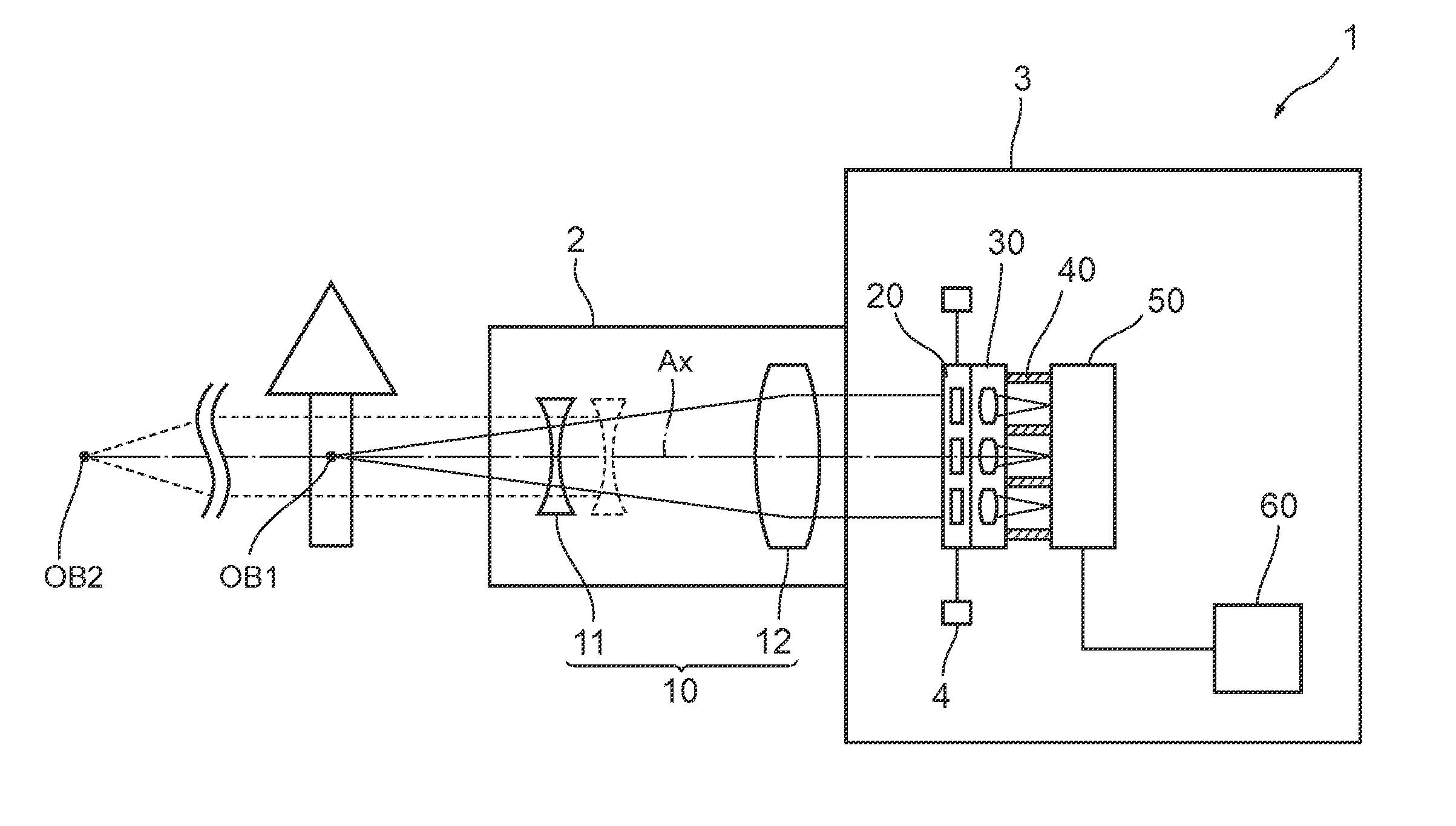
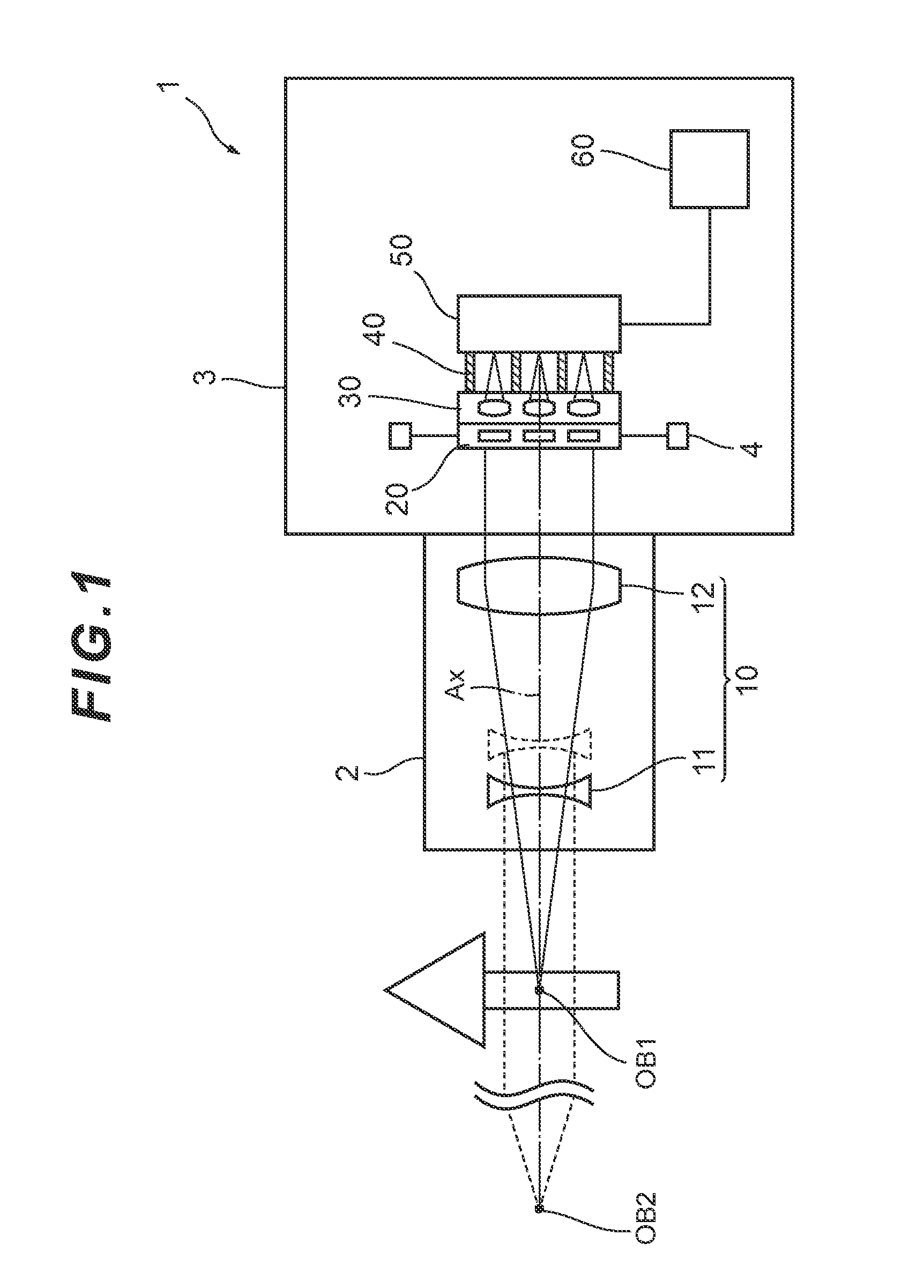
[0058]In the imaging device 1 of Embodiment 1, an object at a finite distance OB1 or an object at infinity OB2 is focused by moving the first lens group 11 along the optical axis Ax using a lens drive device (not illustrated). An operation when the object at a finite distance OB1 is focused will be described. The operation in the case when the object at infinity OB2 is focused is the same as the case when the object at a finite distance OB1 is focused, therefore description thereof is omitted.

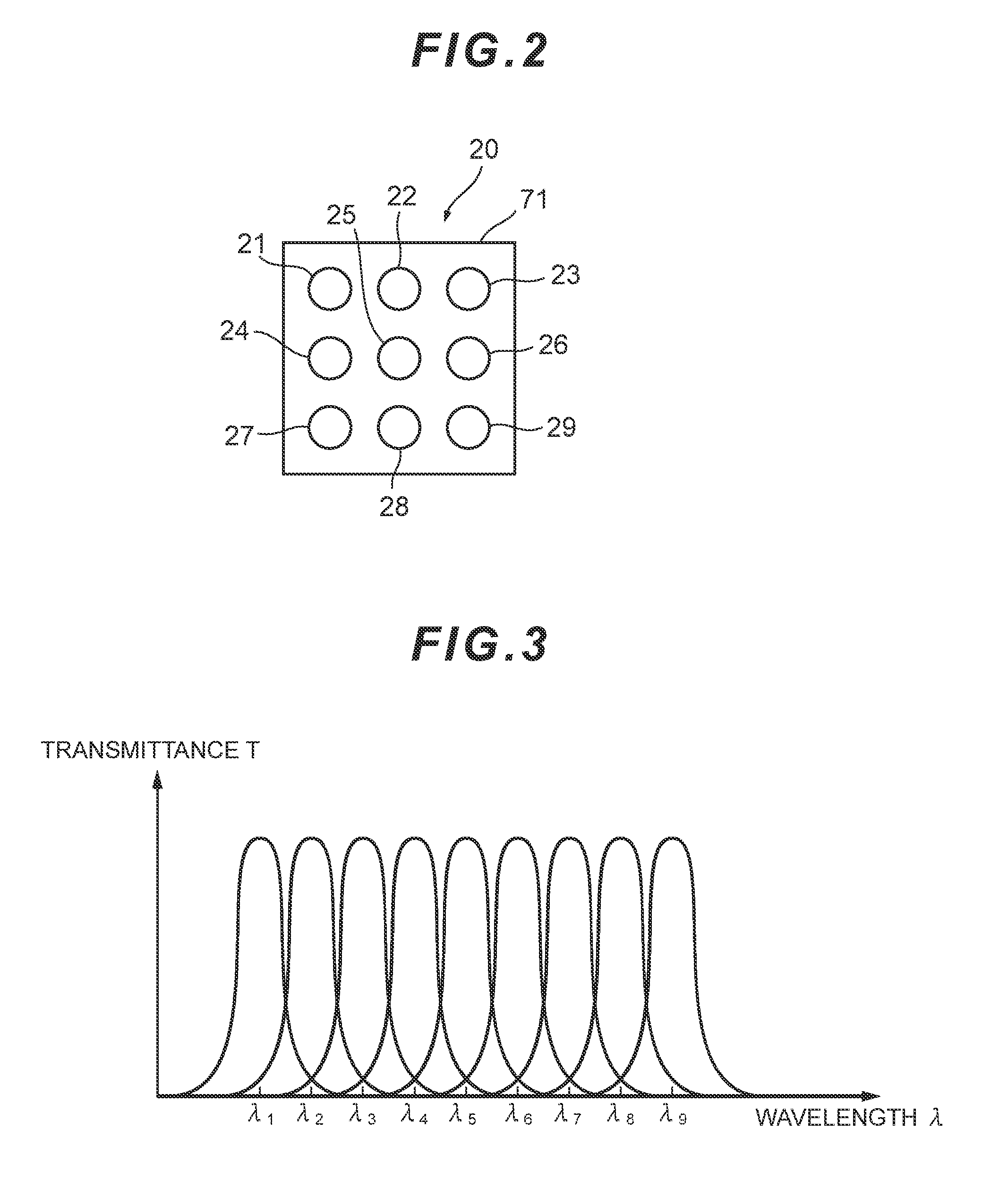
[0059]Luminous flux from the focused object at a finite distance OB1 transmits through the first lens group 11 and the second lens group 12, and is collimated into a parallel luminous flux when emitted from the second lens group 12. The parallel luminous flux emitted from the front optical system 10 passes one of the first spectral filter 21 to the ninth spectral filter 29 of the spectral filter array 20, and reaches the small lens array 30. Each of the first small lens 31 to the ninth small le...

embodiment 2

[0077]In the imaging device 101 of Embodiment 2, an object at a finite distance OB1 or an object at infinity OB2 is focused by moving the first lens group 111 by a lens drive device (not illustrated) along the optical axis Ax. An operation when the object at a finite distance OB1 is focused will be described. The operation in the case of focusing on the object at infinity OB2 is the same as the case of focusing on the object at a finite distance OB1, therefore description thereof is omitted.

[0078]The luminous flux from the focused object at a finite distance OB1 transmits through the first lens group 111 and the second lens group 112, and becomes parallel luminous flux when emitted from the second lens group 112. The parallel luminous flux emitted from the front optical system 10 passes one of the first spectral filter 21 to the ninth spectral filter 29 of the spectral filter array 20 and reaches the small lens array 30. Each of the first small lens 31 to the ninth small lens 39 of ...

embodiment 4

[0119]Table 1 shows the lens data of the imaging optical system 340A of In the lens data in Table 1, the surface number indicates a sequential number of each lens surface counted from the object side, R denotes the radius of curvature of each lens surface, D denotes a distance from each lens surface to the next lens surface, E denotes an effective diameter of each lens surface, nd denotes a refractive index at the d-line (wavelength λ: 587.6 nm), and νd denotes an Abbe number at the d-line (wavelength λ: 587.6 nm). The radius of curvature R=∞ indicates a plane, and the refractive index of air nd=1.0000 is omitted. The units of the radius of curvature R, the surface distance D and the effective diameter E are “mm”. Each radius of curvature R of surface 1 to surface 10 in Table 1 corresponds to each symbol R1 to R10 assigned to surface 1 to surface 10 as shown in FIG. 20.

[0120]

TABLE 1SurfacenumberRDEndvd1∞1.004.01.516863.9 (spectral filter)2∞14.004.03∞1.004.01.516863.94∞0.014.01.6(Ad...


PUM


Abstract

Provided is an imaging device (1) having: a front optical system (10) that transmits light from an object; a spectral filter array (20) that transmits light from the front optical system (10) via a plurality of spectral filters; a small lens array (30) that transmits the light from the plurality of spectral filters via a plurality of small lenses respectively, and forms a plurality of object images; a picture element (50) that captures the plurality of object images respectively; and an image processor (60) that determines two-dimensional spectral information on the object images based on image signals output from the picture element (50). The front optical system (10) is configured to transmit the light from the focused object to collimate the light into a parallel luminous flux.

Description

TECHNICAL FIELD[0001]The present invention relates to an imaging device that acquires optical information, such as spectrum and Stokes parameter information, in an object image by a single imaging process.TECHNICAL BACKGROUND[0002]A multi-band camera is an example of an imaging device (e.g. see Patent Document 1). According to an aspect of the multi-band camera, a prism in which a plurality of light refraction planes, having normal lines in different directions with respect to the optical axis of the optical system, is created, is disposed in a position corresponding to an aperture stop of the optical system. By deflecting the plurality of separated luminous flux in different directions respectively using this configuration, object images of the same number as light refraction planes are formed on different image forming positions on an imaging plane for the same object. Different spectral filters, corresponding to the plurality of object images respectively, are disposed immediatel...

Claims


Application Information

Patent Timeline
Patent Type & Authority Patents(United States)
IPC IPC(8): G02B13/00G02B5/20H04N5/225H04N5/232
CPCG02B13/0015G02B5/20H04N5/2254H04N5/23212G03B11/00G03B15/00G01J3/28G01J3/2803G01J3/2823G01J3/36G01J3/0229G01J3/0262H04N23/55H04N23/67H04N23/11G01J3/0208G01J2003/2806G02B3/0056G02B5/201G02B9/64G02B27/0025G03B13/32G03B17/14
Inventor KATSUNUMA, ATSUSHIKODAMA, KENICHI
Owner NIKON CORP
Why Eureka
Try Eureka