Aircraft vapour trail control system

a control system and vapour trail technology, applied in the direction of efficient propulsion technologies, machines/engines, instruments, etc., can solve the problems of increasing fuel burn, reduce the efficiency of one or more engines, reduce the range of ambient conditions, and weaken the

Active Publication Date: 2016-07-26
ROLLS ROYCE PLC
View PDF15 Cites 10 Cited by
  • Summary
  • Abstract
  • Description
  • Claims
  • Application Information

AI Technical Summary

Benefits of technology

[0009]The present invention is beneficial because different portions of the airframe will induce different contributions to the wake caused by the aircraft. It has been found that the location of the engine exhaust flow relative to certain portions or flow phenomena of the aircraft wake can reduce a vapour trail characteristic compared to other locations on the airframe. The invention may reduce the optical depth of one or more vapour trail formed by engine exhaust flow. The invention may reduce the net / collective optical depth for the plurality of aircraft engines, e.g. by reducing optical depth on at least one engine whilst possibly increasing optical depth on one or more further engine, but typically by a lesser magnitude.
[0015]The controller may adjust the soot emissions of one or more engine at a greater distance from a vortical wake flow region in an opposite sense to one or more engine that is closer to a vortical wake flow region. The controller may reduce the soot emissions of one or more engine at a greater distance from a vortical wake flow region and / or increase the soot emissions of one or more engine that is closer to a vortical wake flow region.
[0027]The controller may vary the thrust produced by each engine such that the thrust contribution by one or more engine on opposing sides of the airframe centreline is within a predetermined thrust threshold or threshold thrust difference, such as a thrust asymmetry threshold. A thrust asymmetry threshold may be predetermined or calculated by the controller. The controller may vary the thrust produced by each engine so as to balance the thrust contribution by one or more engine on opposing sides of the airframe. The invention beneficially allows the efficiency of one or more engine to be reduced in order to reduce the range of ambient conditions in which the engine can form a contrail, whilst ensuring that the aircraft thrust requirements are met.
[0028]Although airframe wake exerts a relatively weak effect on contrail formation, it can be applied at any time during contrail formation by the controller as required to reduce the climate impact of the contrails. It has also been found that varying of the engine operating point, and thereby influencing the engine efficiency, can also be used to provide a contrail suppression effect under certain ambient conditions. Thus the invention may be used not only to reduce the severity of contrail whilst forming but also to enable an aircraft to remain contrail-free at its current / desired flight-level under certain ambient conditions. Thus the invention may beneficially reduce the need to alter other aspects of engine operation and / or flight path to mitigate / suppress contrail formation.
[0030]Each fuel source may comprise a different fuel composition. The plurality of fuel compositions may each comprise a different aromatic content and / or specific energy. The controller may beneficially apportion the different fuels to better effect, e.g. to make best use of a scarcer fuel composition, as compared to a default, or more plentiful, fuel composition.

Problems solved by technology

However, in addition to the added complexity for air traffic control and pilots, the re-routing of aircraft away from predetermined flight paths will cause increased fuel burn, not only by increasing duration and distance travelled, but also by causing departure from optimal cruise conditions of the aircraft engines.

Method used


Image

  • Aircraft vapour trail control system
  • Aircraft vapour trail control system
  • Aircraft vapour trail control system

Examples


Embodiment Construction

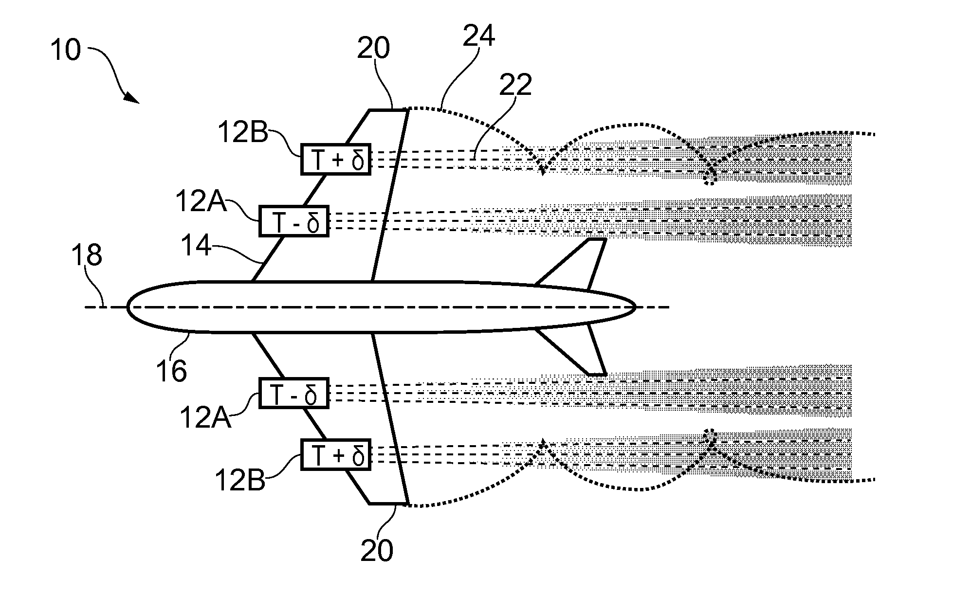
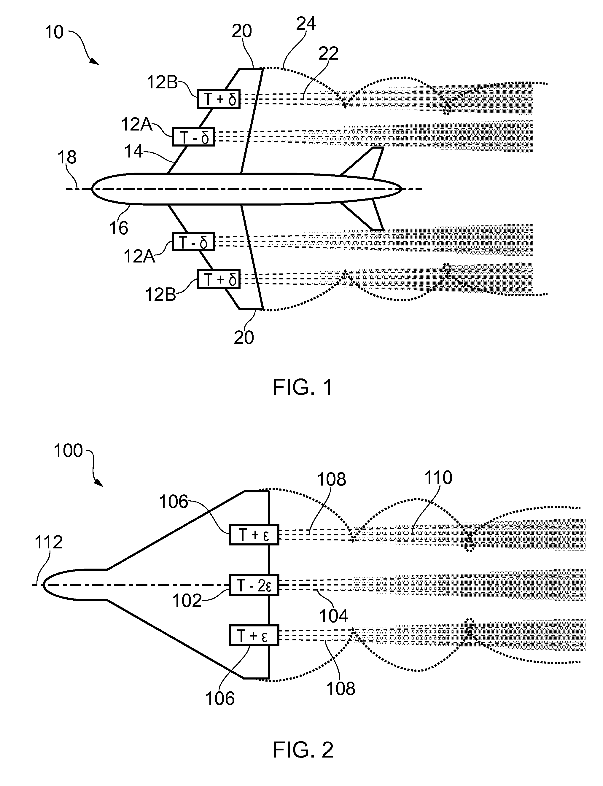
[0056]During operation of an aircraft engine, contrail formation can occur as engine exhaust gases mix with ambient air. The number density of condensation nuclei in the engine exhaust plume will influence the size distribution of ice crystals in the young contrail. Specifically, the greater the number density of condensation nuclei then the smaller will be the initial size of formed ice crystals (and the greater will be the optical depth of the contrail at that point). The persistence of a contrail once formed is influenced by ambient conditions, and, in particular the level of ice saturation of ambient air.

[0057]The term ‘mitigation’ is used herein to refer to the suppression of contrail formation and / or the advantageous modification of one or more contrail characteristic, for example contrail optical depth.

[0058]In essence, this invention achieves a contrail mitigation effect by selectively altering the exhaust emissions of each engine according to proximity to flow phenomena cau...


PUM


Abstract

The invention concerns an aircraft propulsion control system for an aircraft with a plurality of gas turbine engines mounted at different spaced positions relative to an airframe. One or more sensor is arranged to sense a condition indicative of vapor trail formation by an exhaust flow from one or more of the plurality of engines. A controller is arranged to be responsive to thrust demand for the aircraft and selectively to control each of the engines so as to modify the exhaust flow of at least one engine relative to at least one further engine according to the positions of the engines on the airframe. The proximity of an engine to a vortical wake flow created by the airframe may be used to determine suitable exhaust flow modifications. The controller may output a separate throttle control signal to each engine and / or may adjust the fuel composition supplied to each engine.

Description

BACKGROUND OF THE INVENTION[0001]The present invention relates to aircraft propulsion systems, and more particularly to control systems for mitigating contrail formation.[0002]Contrails, also known as condensation trails or vapour trails, are line-shaped ice-clouds that appear behind aircraft under certain circumstances. The formation of a contrail depends on a number of factors, including: ambient temperature, humidity and pressure; the efficiency of the aircraft's engines; and the properties of the fuel burned in the engines.[0003]A contrail, once formed, will typically dissipate within a minute or so, unless the ambient air is supersaturated with respect to ice, in which case the contrail may persist. A persistent contrail will grow over time to resemble natural cirrus cloud, both in size and optical properties, and is referred to as “contrail-cirrus”. Line-shaped contrails and contrail-cirrus are collectively referred to as “aviation-induced cloudiness” (AIC). Contrail-cirrus is...

Claims


Application Information

Patent Timeline
Patent Type & Authority Patents(United States)
IPC IPC(8): G06F7/00B64D31/06B64D33/04
CPCB64D31/06B64D33/04F02C9/16F05D2270/0831Y02T50/60F02C6/00F02C9/28F02C9/40F02C9/42F02C9/48F05D2270/13
Inventor SWANN, PETER
Owner ROLLS ROYCE PLC
Why Eureka
Try Eureka