Methods and apparatus for gas-phase reduction/oxidation processes

a reduction/oxidation and gas-phase technology, applied in the direction of lighting and heating apparatus, gas-gas reaction processes, liquid-gas reaction of thin-film type, etc., can solve the problems of reduced process efficiency, undesirable oxidation and reduction steps of redox cycles, and reduced process efficiency, so as to achieve fast overall kinetics, efficient heat and mass transfer, and increase surface area

Active Publication Date: 2016-07-26
UNIV OF COLORADO THE REGENTS OF
View PDF2 Cites 2 Cited by
  • Summary
  • Abstract
  • Description
  • Claims
  • Application Information

AI Technical Summary

Benefits of technology

[0012]As set forth in more detail below, in accordance with various embodiments of the disclosure, reduction and oxidation cycles are performed under isothermal (or substantially isothermal) conditions, such that significant heating or cooling between the respective cycles is not required. This allows faster, more efficient cycling between the reduction and oxidation steps and less wear on the equipment and materials used for the process. In accordance with various embodiments, the oxidation reaction of the isothermal redox reaction is typically much faster than the reduction reaction, such that product gas(es) of the oxidation stage are produced first and / or can easily be separated from gas(es) produced during the reduction reaction.
[0017]In different aspects, the disclosure provides methods and apparatus for simultaneously conducting both steps of a gas-phase redox reaction, where concentrated solar energy provides thermal energy to the reaction. Use of a two-step process can eliminate the need to perform high-temperature separation of gaseous reaction products. In different embodiments, the methods and apparatus of the disclosure can be used to simultaneously conduct both steps of a water and / or carbon dioxide splitting process. In an embodiment, both steps of the two-step reaction are conducted in the same reaction chamber designed to allow efficient recuperation of heat between the two reaction steps. The solar reactors and methods described herein can be used with any of the isothermal methods described herein or with other methods.
[0021]Desired reactor tube assembly temperatures may be achieved through consideration of several factors including the thermal energy provided to the reactor, heat transfer within the cavity and tubes, the endothermicity of the reaction during the reduction step and the flow rate of the reactant to be reduced during the metal oxide oxidation step. In accordance with some exemplary systems, two sets of reactor tube assemblies are exposed to approximately the same level of intensity of solar radiation, so that the temperature of the reactor tube assemblies running the oxidation reaction is controlled primarily through the mass flow of the reactant to be reduced (e.g. water or carbon dioxide). Heat transfer within the cavity can be influenced by the design and arrangement of the reactor tube assemblies inside the cavity-receiver. A desired position of the tubes and the number and dimensions of the tubes can be determined by solving the energy conservation equation that couples heat transfer (especially radiative transfer) and reaction enthalpies. The reactor tubes need not be separated from each other by dividing walls or similar structures; this facilitates transfer of heat within the cavity. With such an arrangement, the sensible heat of the solid components during the switching of modes may be transferred among tubes and kept inside the cavity, achieving high internal recuperation of heat.
[0023]In accordance with yet additional exemplary embodiments, a multi-tube cavity reactor includes more than two reactor tube assemblies for splitting gas-phase reactants. Exemplary reactor tube assemblies include an inner tube and an outer tube. A bottom end of the outer tube may be closed and the bottom end of the inner tube may be porous, establishing a stagnation flow reactor configuration. Metal oxide or reduced metal oxide on a porous support structure may be located within the annular region between the two tubes, allowing for efficient heat and mass transfer and consequently, fast overall kinetics. The inner tube may be packed with porous media providing increased surface area for heat transfer, for example, to drive the vaporization of water to steam. By way of example, a reactant may flow downward through the inner tubes of the tube assemblies operating in oxidation mode before exiting the inner tube and moving upwards through the supported reduced metal oxide in the annular space between the tubes. The product of the oxidation reaction exits the annular space between the tubes in the oxidation tube assemblies. Inert gas or air may be provided to the inner tubes of the tube assemblies operating in reduction mode. This inert gas or air acts as a sweep gas help remove oxygen gas, the product of the reduction reaction, from the reduction tube assemblies.
[0024]In accordance with yet further embodiments, the difference between the oxidation and reduction temperatures (or the maximum of the oxidation and reduction temperature ranges) is less than 500° C., 300° C., 100° C., 50° C., or substantially 0° C. or from 100° C. to 500° C., 100° C. to 300° C., or 0° C. to 50° C. Minimizing the difference between the oxidation and reduction temperatures can simplify the recuperation of heat during the redox steps. In accordance with exemplary embodiments, the reduction temperature is from 1000° C. to 1500° C. (or the reduction temperature range falls within the range from 1000° C. to 1500° C.). In other embodiments, the reduction temperature range may be 1100° C. to 1500° C. or 1200° C. to 1400° C. In accordance with various aspects, the oxidation temperature is from 800° C. to 1400° C. (or the oxidation temperature range falls within the range from 800° C. to 1400° C.).

Problems solved by technology

This difference in temperature requires a cool-down followed by a heat-up step, both of which take time and inherently result in sensible heat losses and reduced efficiency of the process.
Running the oxidation and reduction steps of the redox cycles at substantially different temperatures may be undesirable for several reasons.
For example, systems running such cycle exhibit heat loss with each temperature change.
In addition, altering the temperature of the system to run each cycle requires additional time to heat or cool the system that reduces the number of cycles that can be performed during a given period.
And, the temperature cycling can cause materials used in the reaction to degrade more quickly than if the reaction could be run at substantially isothermal conditions.

Method used


Image

  • Methods and apparatus for gas-phase reduction/oxidation processes
  • Methods and apparatus for gas-phase reduction/oxidation processes
  • Methods and apparatus for gas-phase reduction/oxidation processes

Examples


Embodiment Construction

[0039]The description of exemplary embodiments of the present disclosure provided below is merely exemplary and is intended for purposes of illustration only; the following description is not intended to limit the scope of the invention disclosed herein. Moreover, recitation of multiple embodiments having stated features is not intended to exclude other embodiments having additional features or other embodiments incorporating different combinations of the stated features.

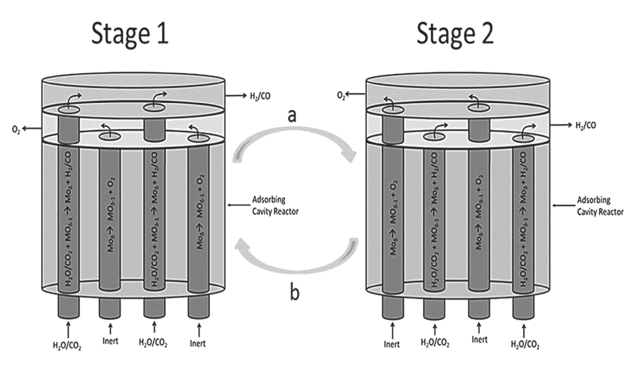
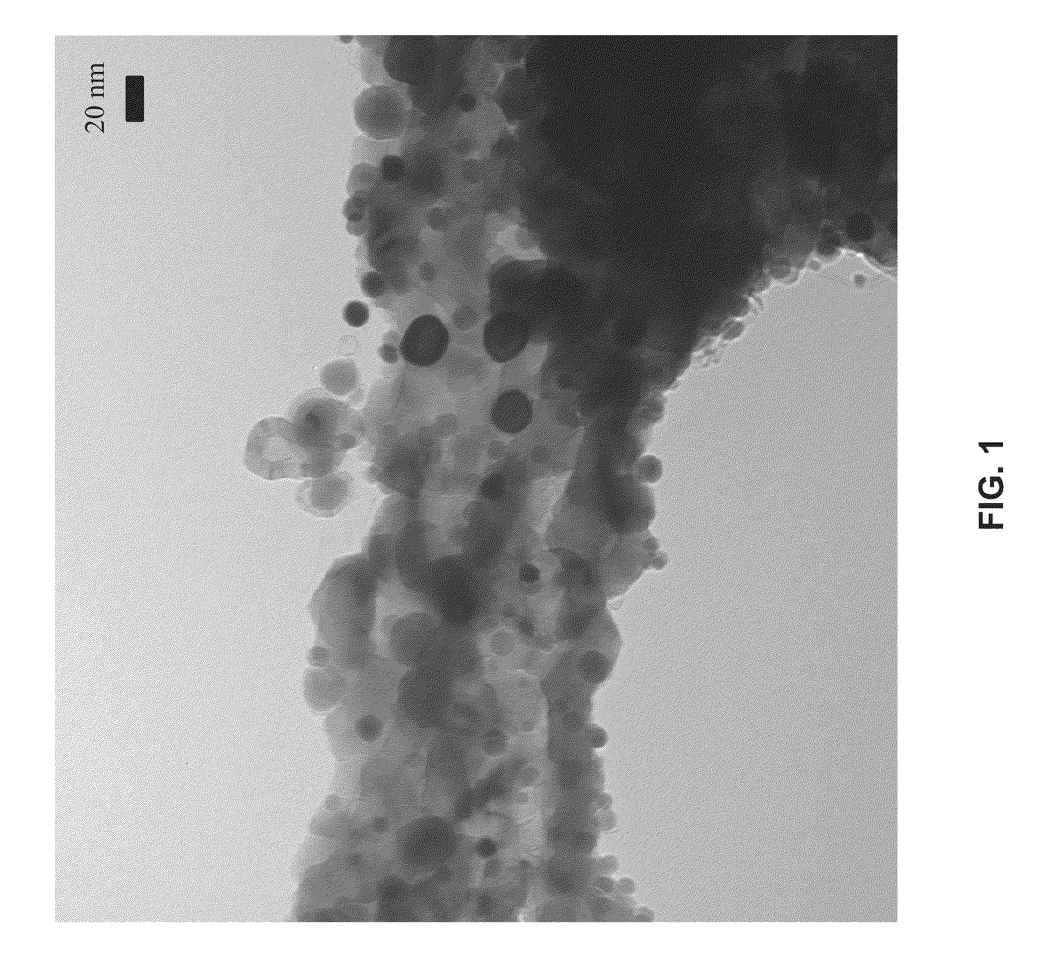
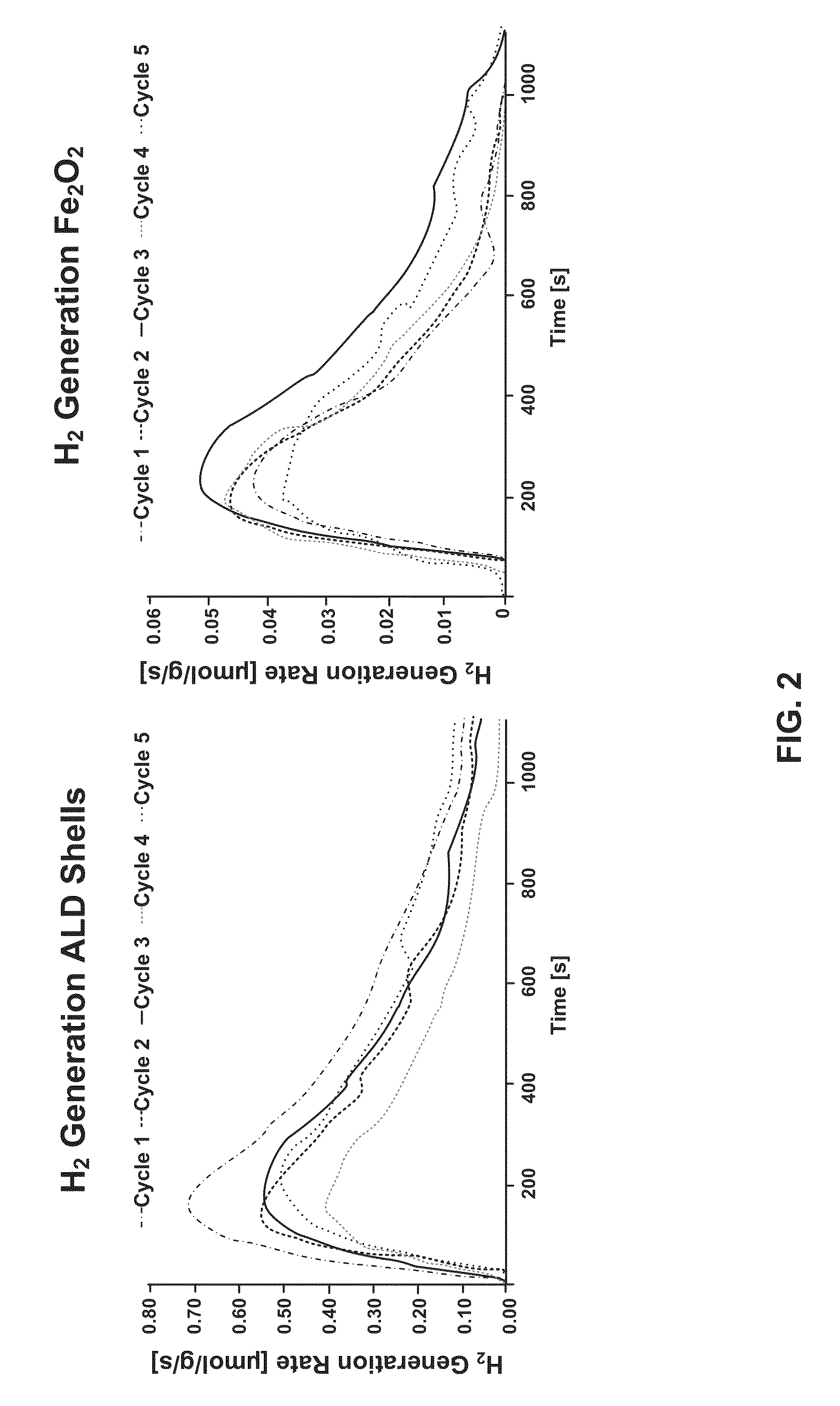
[0040]The present disclosure provides an improved method and an apparatus for splitting gas-phase reactants using redox reactions under substantially isothermal conditions and / or using a solar reactor system. As set forth in more detail below, the method and apparatus include an active redox material (e.g., high surface area material selected from the group consisting of one or more of: ceria, M-ferrite and hercynite material) to facilitate splitting of the gas phase reactant.

[0041]Metal oxides suitable for use with...


PUM

PropertyMeasurementUnit
temperatureaaaaaaaaaa

Abstract

A method and apparatus for gas-phase reduction / oxidation is disclosed. The apparatus includes a reactor including at least one reactor tube or containment vessel with active redox material within the reactor tube or containment vessel, a first reactant gas or vacuum for reducing the active redox material, and a second reactant gas for oxidizing the active redox material. The method may be run under substantially isothermal conditions and / or energy supplied to the apparatus may include solar energy, which may be concentrated.

Description

CROSS REFERENCE TO RELATED APPLICATIONS[0001]This application claims the benefit of provisional application No. 61 / 620,891, entitled METHOD AND APPARATUS FOR GAS-PHASE REDUCTION / OXIDATION PROCESS, and filed Apr. 5, 2012, the contents of which are incorporated herein by reference to the extent such contents do not conflict with the present disclosure.FIELD OF INVENTION[0002]The present invention generally relates to reduction / oxidation (redox) methods and apparatus. More particularly, the invention relates to substantially isothermal redox processes to split gas-phase reactants and to solar thermochemical reactor technology for effecting redox reactions.BACKGROUND OF THE INVENTION[0003]Various redox processes can be used to split gas-phase reactants. For example, hercynite, ceria, and M-ferrite redox cycles may be used to split water (vapors) and CO2. The hercynite cycle can be represented by the following equations.[0004]Hercynite cycle:Reduction: CoFe2O4+3Al2O3→CoAl2O4+2Fe2AlO4+½O2...

Claims


Application Information

Patent Timeline
Patent Type & Authority Patents(United States)
IPC IPC(8): C01B3/06C01B13/02C01B3/04C01B31/18F24J2/07F24J2/48C01B32/40F24S20/20
CPCC01B3/061C01B3/045C01B13/0207C01B31/18F24J2/07F24J2/485Y02E10/41Y02E60/364Y02P20/134F24S20/20F24S70/225Y02E10/40Y02E60/36Y02P20/133
Inventor LICHTY, PAULMUHICH, CHRISTOPHERARIFIN, DARWINWEIMER, ALAN W.STEINFELD, ALDO
Owner UNIV OF COLORADO THE REGENTS OF
Why Eureka
Try Eureka