Ignition system

a technology of ignition system and ignition system, which is applied in the direction of ignition control, induction energy storage installation, other installations, etc., can solve the problems of unpredictable load situation, unpredictable heat amount, and common ignition system failure (or limit the lean operation)

Inactive Publication Date: 2016-07-26
DELPHI INT OPERATIONS LUXEMBOURG S A R L +1
View PDF12 Cites 28 Cited by
  • Summary
  • Abstract
  • Description
  • Claims
  • Application Information

AI Technical Summary

Benefits of technology

[0017]It shall be appreciated that the ignition system is designed to generate, for a given ignition event, a current through the secondary winding by way of a control circuit that is configured to first—in an initial phase—energize and deenergize the first primary winding (LP1) to establish a first electrical arc across the gapped electrodes (initial phase) and, when the current in the secondary winding reaches, or drops below, a predetermined current threshold—in a second phase—repeatedly energize and deenergize the second primary winding (LP2) to establish a plurality of second electrical current pulses into the existing arc across the gapped electrodes in order to maintain the burn phase. This mode of operation allows the generation of current pulses in a time sequence such that the second phase can be maintained infinitely. An extended burn phase can thus be obtained without the need for a new dielectric break down.
[0019]The LP1 / LSEC pair provides the charge and initial burn of the spark event. The LP2 / LSEC pair is active in the second phase, which is triggered in function of the current in the secondary winding (when the threshold condition is met), and provides a continuous burn phase, hence creating a continuous spark. The second phase is thus initiated during the initial arc, and preferably pushes power peaks into the latter in order to provide a pulsed supply of energy into the burn process. Moreover, in case the energy originating from the LP1 / LSEC pair is depleted the burn process continues. This is possible because sufficient afterglow exists between the electrode gaps for a short time period after one single current pulse. In other words, the present invention exploits the existing afterglow to provide the continuous burn.
[0020]Overall, an efficient ignition system is proposed, providing a unipolar current with a reliable and simple design, requiring only one transformer with two primary windings coupled to one secondary winding.
[0021]By contrast to the ignition system of EP 2 141 352, the present ignition system is thus configured and operated so that the energy transferred into the secondary winding results in a unipolar current into the spark-plug and unipolar voltage across the spark-plug electrodes. This makes it possible to use a diode in series with the secondary coil and spark plug to prevent early make.
[0025]The repeated energizing and deenergizing of the second primary winding (second phase) is advantageously driven by a pulse width modulation (PWM) signal, which is enabled when the threshold condition on the secondary current is met. This allows a reduction of thermal losses inside the transformer and associated electronics.

Problems solved by technology

For operating with lean gasoline mixtures, the common ignition systems fail (or limit the lean operation) because of the typical discharge nature of the stored energy to the load interaction.
The depletion of the remaining stored energy of the transformer into the spark, which itself interacts heavily with its surroundings in the combustion chamber, creates unpredictable load situations.
Accordingly, unpredictable heat amounts are delivered, in particular at unfavorable timings and unexpected locations.
This consequently tends to result in statistical scattering of the combustion pressure, which contributes to unfavorable engine-out emissions as well as uncontrollability also referred to as instability of the combustion.
To a certain extent this malfunction is caused by the depletion of the energy of the transformer, thus the collapsing of the delivered electrical power into the spark.
This is leading occasionally to very timely tight stable combustion situations, were smallest disturbances create increased pressure scatter traces and thereby lead to unstable lean operation conditions.
A practical problem of this system is however the alternating polarities of the current in the secondary winding, which prevents the use of a diode in the line leading from the secondary winding terminal to the spark plug.
Absent such diode, it is not possible to prevent a so-called “early make” spark, which typically occurs at the moment the primary coil is switched to the power source to start the charging phase.
The occurrence of early make spark triggers ignition at undesired timings at low engine pressure.

Method used


Image

  • Ignition system
  • Ignition system
  • Ignition system

Examples


Embodiment Construction

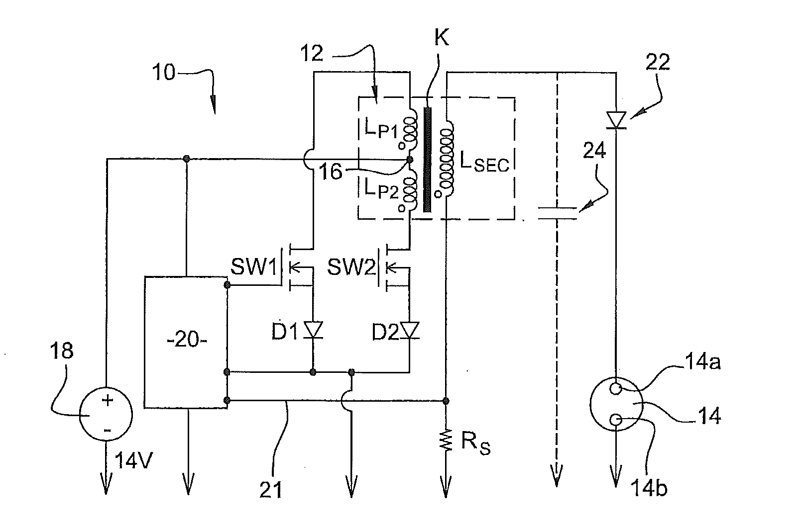
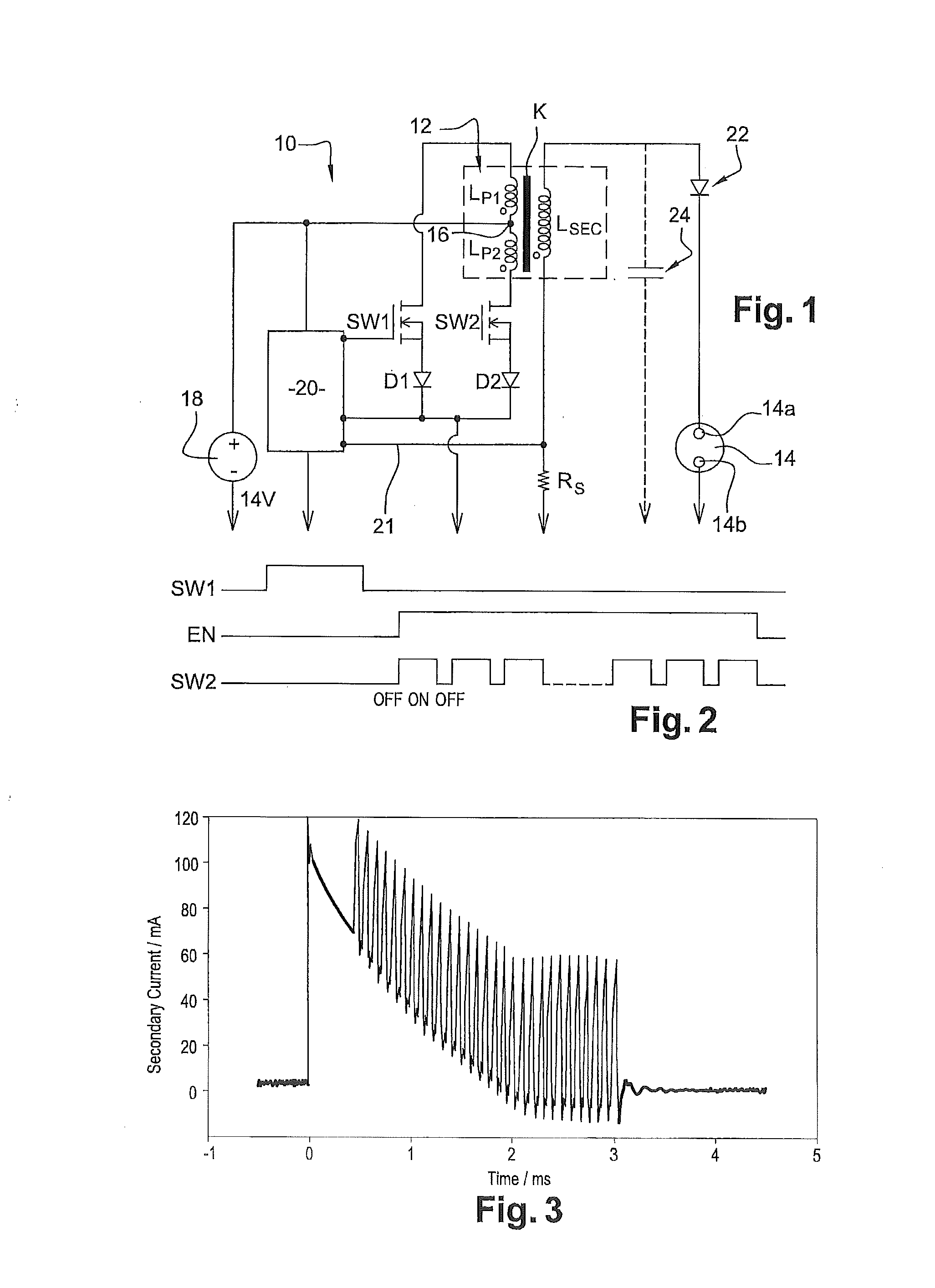
[0035]With reference to FIG. 1, a preferred embodiment of the present ignition system 10 is shown in electrical schematic, comprising a dual primary winding ignition transformer 12, or ignition coil, servicing a single set of gapped electrodes 14a and 14b in a spark plug 14 such as might be associated with one combustion cylinder of an internal combustion engine (not shown).

[0036]In addition to the two primary windings noted LP1 and LP2, ignition coil 12 comprises a secondary winding LSEC and a common magnetic coupling K1; the three windings are magnetically coupled.

[0037]The system 10 is configured so that the two ends of the first and second primary windings LP1, LP2 may be switched, in an alternative manner, to a common ground such as a chassis ground of an automobile by electrical switches SW1, SW2. The switches SW1 and SW2 may each take the form of an IGBT (insulated gate bipolar transistor) or other appropriate semiconductor-switching device.

[0038]Preferably, the turn ratio of...


PUM


Abstract

An ignition system for an internal combustion engine includes an ignition transformer with two primary windings. The ignition system is designed to generate, for a given ignition event, a unipolar current through the secondary winding by way of a control circuit that is configured to first energize and deenergize the first primary winding to establish a first electrical arc across the spark-plug electrodes and, when the current in the secondary winding reaches, or drops below, a current threshold, repeatedly energizes and deenergizes the second primary winding to establish a plurality of second current pulses across the electrodes in order to maintain the burn phase.

Description

FIELD OF THE INVENTION[0001]The present invention generally relates to an ignition system for an internal combustion engine and more particularly to an ignition system comprising an ignition transformer with two primary windings.BACKGROUND OF THE INVENTION[0002]The combustion of gasoline in reciprocal engines requires, as it is well known, a flame initiation device commonly called an ignition system. An ignition systems consists of two main components:[0003]a spark plug; and[0004]an ignition coil or transformer.[0005]The spark plug represents the direct interface to the flame kernel itself via its firing face and represents an isolated electrical feed-through into the combustion chamber. The task of the ignition transformer is to provide the suitably shaped energy to initiate the combustion. This is conventionally split into two consecutive and distinct phases.[0006]The first phase stores electrical energy inside the inductors of the transformer and the next phase releases the previ...

Claims


Application Information

Patent Timeline
Patent Type & Authority Patents(United States)
IPC IPC(8): F02P15/10F02P15/12F02P9/00F02P3/04F02P3/055F02P17/12
CPCF02P3/0407F02P3/0442F02P3/055F02P9/002F02P9/007F02P15/10F02P15/12F02P2017/121
Inventor HEISE, VOLKERLOENARZ, MARCOLORENZ, FRANK
Owner DELPHI INT OPERATIONS LUXEMBOURG S A R L
Why Eureka
Try Eureka