Method, apparatus, computer program product, computer readable medium and system for fast feedback and response handling in wireless networks

a wireless network and feedback technology, applied in the field of communication systems, can solve the problems of not being able to improve, adding spectrum, but also eventually outpacing the demand, and limiting the available spectrum below 6 ghz, so as to reduce modulation and coding schemes, increase the spreading factor, and increase the repetition factor

Active Publication Date: 2016-08-23
NOKIA TECH OY
View PDF13 Cites 17 Cited by
  • Summary
  • Abstract
  • Description
  • Claims
  • Application Information

AI Technical Summary

Benefits of technology

[0026]In the method of the first embodiment, the tailoring may comprise at least one of beamforming, increasing a spreading factor, decreasing a modulation and coding scheme, or increasing a repetition factor.
[0046]In the third embodiment, the at least one memory and the computer program code may also be configured to, with the at least one processor, cause the apparatus at least to tailor by at least one of beamforming, increasing a spreading factor, decreasing a modulation and coding scheme, or increasing a repetition factor.

Problems solved by technology

However, innovations in cellular air-interface design, culminating in the third generation partnership project (3GPP) long term evolution (LTE), provide spectral efficiency performance that may not be able to improve at a corresponding rate.
This added spectrum, however, may also eventually be outpaced by the demand.
Moreover, the available spectrum below 6 GHz is limited and there may be practical limits to how small cells can shrink.
Unlike traditional cellular systems, electromagnetic (EM) waves in for example the millimeters bands (for example, for frequencies above 6 GHz) do not benefit from diffraction and dispersion, making it difficult for them to propagate around obstacles.
Moreover, such millimeter waves also suffer higher penetration loss in some materials.
As a result, millimeter transmissions may be much more likely to encounter shadowing effects than microwave transmission.
Millimeter transmissions may also have less favorable link budgets due to lower power amplifier (PA) output powers and greater pathloss at these higher frequencies.
Reliance on these array gains can complicate link acquisition and maintenance.
Traditional cellular systems, such as 3G LTE, cannot simply be upbanded and expected to function in the millimeter bands.
With narrow beams, the user equipment may lose radio connection to the access point in case of blockage or misalignment.
This may be due to, for example, obstruction between the user equipment and access point by objects, such as humans, trees, cars, or the like.
Misalignment may be due to misalignment of the antenna array beams caused by wind-induced vibrations at the access point, or beam misalignment due to changes in user orientation, for example, due to how a device is held.
A LTE system which is simply upbanded to 70 GHz would not provide adequate coverage or economy.
LTE relies on radio wave diffraction around obstacles and therefore an LTE millimeter wave system would not achieve a reasonable coverage reliability target, for example 90% coverage reliability.
LTE, which employs OFDM modulation, conventionally requires a significant Power Amplifier (PA) backoff making the solution less desirable at 70 GHz.
Using current technology, the processing time for this user equipment will remain 3 ms, which is significantly longer than the subframe length and therefore likely to introduced large latency when retransmission is required.
Even with significant improvement in user equipment processing capability, the reduced processing time (e.g. 1 ms) may still be significantly larger than the subframe size and can lead to unnecessarily large latency.
Secondly, with mmWave and narrow beams, the user equipment may lose connection to the transmission point, for example, due to blockage or misalignment of the antenna array beams caused by human movement or by wind-induced vibrations at the access point, and may require rapid site selection.
However, the transmission / reception point may require feedback from the user equipment that connection has been lost.
However, this can take a long time due to user equipment processing requirement as discussed above.

Method used


Image

  • Method, apparatus, computer program product, computer readable medium and system for fast feedback and response handling in wireless networks
  • Method, apparatus, computer program product, computer readable medium and system for fast feedback and response handling in wireless networks
  • Method, apparatus, computer program product, computer readable medium and system for fast feedback and response handling in wireless networks

Examples


Embodiment Construction

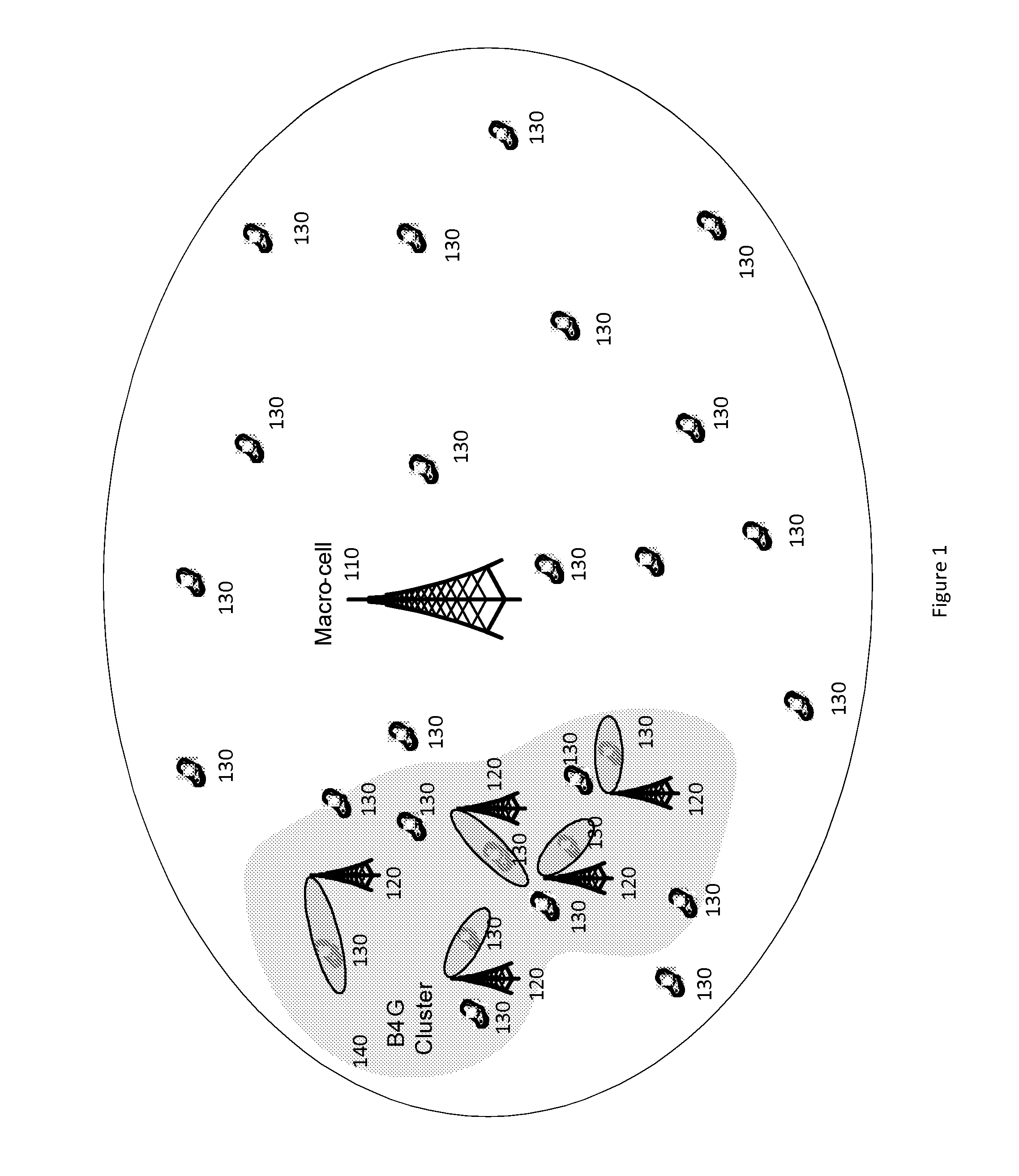
[0085]In mmWave access, a set of co-operating access points or “cluster” of access points, can be deployed to cover an area, for example, a 100 meter radius. A cluster can be used because mmWave may be subject to high shadowing loss and low diffraction, such that each individual coverage area contains multiple shadow regions where radio communication is not supported. Cooperating cluster nodes can be arranged such that these shadowed regions are covered from a unique propagation direction As a result, a user may be covered by multiple access points within the cluster. In addition to mmWave access, LTE in macro-cell type deployment can also be deployed to provide coverage outside the area covered by mmWave access. FIG. 1 illustrates mmWave access deployment and LTE overlay.

[0086]As shown in FIG. 1, a macro-cell 110 may comprise a plurality of access points 120 and numerous user equipment 130. A B4G Cluster 140 may comprise a plurality of the access points 120.

[0087]Rapid re-routing o...


PUM


Abstract

Communication systems may employ transmission of feedback information and responses thereto, on a wireless connection such as a millimeter wave connection. The feedback information itself may be used to influence the beamforming or beam direction used for the transmission of the feedback information. A method can comprise determining a feedback indicator regarding reception of a transmitted waveform. The method can also comprise tailoring, for example beamforming, a signal for transmitting the feedback indicator based on a content of the feedback indicator.

Description

BACKGROUND[0001]1. Field[0002]The invention, in certain embodiments, relates to communication systems which may employ transmission of feedback information and responses thereto, on a wireless connection.[0003]2. Description of the Related Art[0004]Wireless data traffic is projected to grow significantly. However, innovations in cellular air-interface design, culminating in the third generation partnership project (3GPP) long term evolution (LTE), provide spectral efficiency performance that may not be able to improve at a corresponding rate. To meet the growing traffic demand, other approaches may be used, such as increasing the cellular capacity per square meter by either shrinking cell-sizes or acquiring additional spectrum. For example, smaller cells may be implemented through heterogeneous networks of picos and macros, such as for carrier frequencies below 6 GHz, for example LTE heterogeneous network (HetNet). Similarly, 500 MHz of more spectrum is being made available below 5 ...

Claims


Application Information

Patent Timeline
Patent Type & Authority Patents(United States)
IPC IPC(8): H04W36/00H04L1/18H04B7/06H04B7/08H04W16/28H04W36/26H04W72/04
CPCH04B7/0623H04B7/0695H04B7/088H04L1/1812H04W16/28H04W36/26H04W72/042H04B7/0617H04L1/0072H04L1/1819H04L1/1825H04W72/23
Inventor RATASUK, RAPEEPATTHOMAS, TIMOTHYVOOK, FREDERICKGHOSH, AMITABHACUDAK, MARK
Owner NOKIA TECH OY
Why Eureka
Try Eureka