

Catalyst design for heavy-duty diesel combustion engines
a technology for diesel combustion engines and catalysts, applied in physical/chemical process catalysts, metal/metal-oxide/metal-hydroxide catalysts, separation processes, etc., can solve the problems of reduced efficiency, reduced surface area, and large cost of pgm catalysts
- Summary
- Abstract
- Description
- Claims
- Application Information
AI Technical Summary
Benefits of technology
Problems solved by technology
Method used
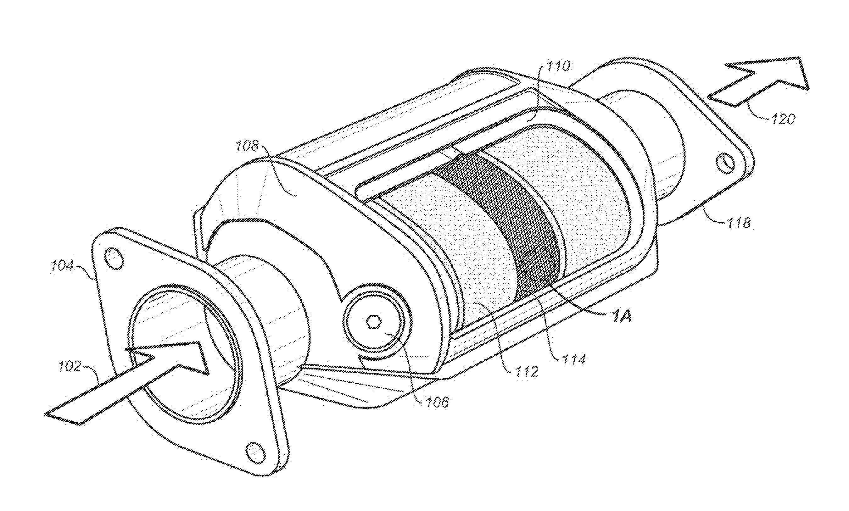
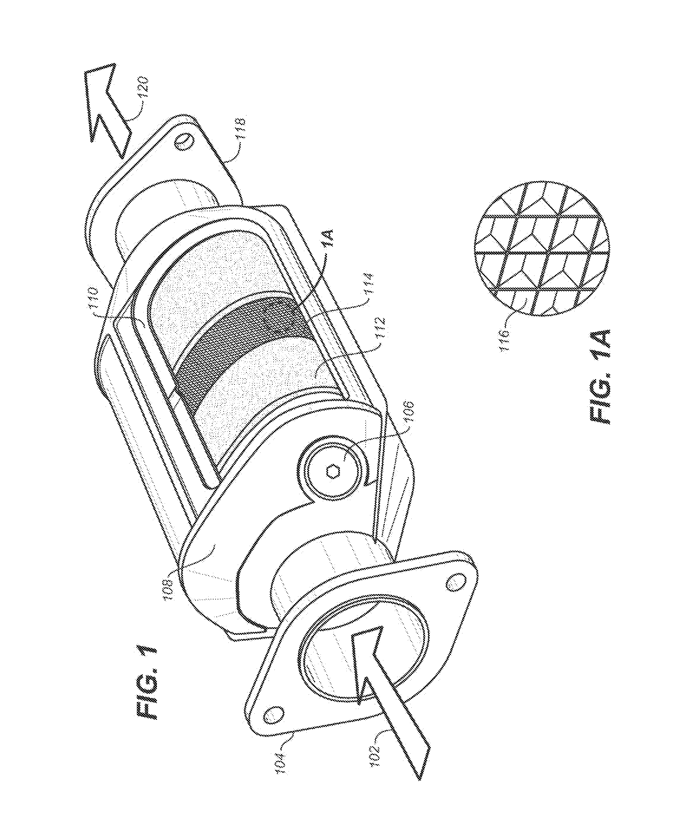
Image

Examples
example 1
Substrate-Catalytic Layer (S-C) Configuration with Two Types of Catalytically Active Material in Catalytic Layer
[0507]In one example configuration, a catalytic washcoat composition applied to a substrate comprises a substrate and a catalytic washcoat layer. The catalytic washcoat layer may comprise about 3 wt % boehmite, about 40 wt % NNm particles with a platinum:palladium weight ratio of 20:1, about 40 wt % NNm particles with platinum:palladium weight ratio of 5:1, and about 17 wt % porous alumina (such as MI-386).
[0508]The ingredients discussed above for the catalytic washcoat composition are mixed with water and acid, such as acetic acid, and the pH is adjusted to about 4. After adjusting the viscosity to the proper levels, this first washcoat is coated onto the substrate. Excess washcoat is blown off and recycled. The coated substrate is then dried and calcined.
example 2
Substrate-First Catalytic Layer-Second Catalytic Layer (S-C1-C2) Configuration with Two Catalytic Layers, Each Comprising a Different Type of Catalytically Active Material
[0509]In one example configuration, a catalytic washcoat composition applied to a substrate comprises a substrate, a first catalytic washcoat layer, and a second catalytic washcoat layer. The first catalytic washcoat layer may comprise about 3 wt % boehmite, about 80 wt % NNm particles with a platinum:palladium weight ratio of 20:1, and about 17 wt % porous alumina (such as MI-386). The second catalytic washcoat layer may comprise about 3 wt % boehmite, about 80 wt % NNm particles with a platinum:palladium weight ratio of 5:1, and about 17 wt % porous alumina (such as MI-386).
[0510]The ingredients discussed above for the first catalytic washcoat composition are mixed with water and acid, such as acetic acid, and the pH is adjusted to about 4. After adjusting the viscosity to the proper levels, this first washcoat i...
example 3
Substrate-First Catalytic Layer-Second Catalytic Layer (S-C1-C2) Additional Configuration with Two Catalytic Layers
[0512]In another example configuration, a catalytic washcoat composition applied to a substrate comprises a substrate, an optional corner fill layer, a first catalytic washcoat layer, and a second catalytic washcoat layer. The substrate contains about 0.8 g / L total platinum group metal loading.
[0513]The optional corner fill layer can be comprised of porous alumina (such as MI-386 particles) and about 3% boehmite, and may optionally also include zeolites. The zeolites can be included in an amount of between 20% and 90% by weight of the solids content of the corner fill layer washcoat, such as about 50%. The optional corner fill layer, when used, is applied in an amount of about 50 g / L to 60 g / L to the substrate.
[0514]The first catalytic washcoat layer may comprise boehmite (about 3 wt %), NNm particles (nano-platinum:palladium alloy on nano-alumina on micro-alumina) with...
PUM
| Property | Measurement | Unit |
|---|---|---|
| weight | aaaaa | aaaaa |
| weight | aaaaa | aaaaa |
| weight | aaaaa | aaaaa |
Abstract
Description
Claims
Application Information