Eureka AIR delivers breakthrough ideas for toughest innovation challenges, trusted by R&D personnel around the world.

Integrated design fluid end suction manifold

a technology of integrated design and fluid end, which is applied in the direction of positive displacement liquid engines, piston pumps, liquid fuel engines, etc., can solve the problems of low value required for pump, devastating damage to suction piping, and low positive suction head availabl

Inactive Publication Date: 2016-11-22
ALTIS INVESTMENTS LLC
View PDF21 Cites 13 Cited by
  • Summary
  • Abstract
  • Description
  • Claims
  • Application Information

AI Technical Summary

Benefits of technology

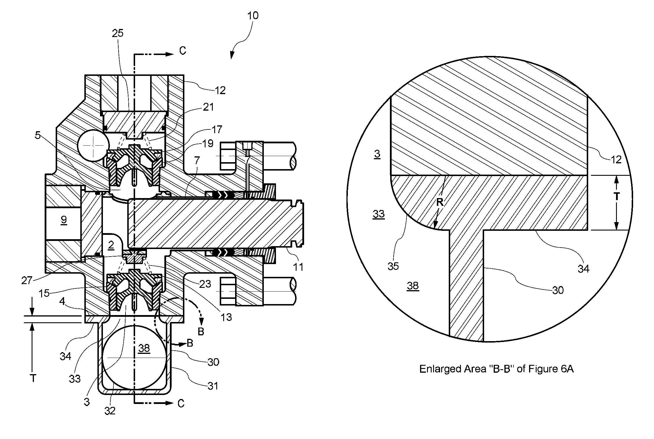
[0013]The present invention continues the integrated design approach utilized by the inventor in previous patent applications. The present invention utilizes a plenum chamber suction manifold design without ducts utilized in a traditional suction manifold. The suction manifold of the present invention allows for bi-directional flow in the manifold and significantly reduces friction and turbulence while maintaining fluid energy. In the plenum chamber design of this invention, the entire suction manifold is located directly below the fluid end block, eliminating all vertical ducts used to feed the suction valves. The plenum chamber design replaces ducts with ports concentric with the suction valves and allows fluid to be fed directly to the suction valve. The suction manifold of the present invention is attached to the bottom of the fluid housing by bolts and a mounting flange located across the top of the chamber. The circumferential edges of the duct-less ports have full radii equal to the thickness of the mounting flange. The radiused edge allows bi-direction flow in the manifold and eliminates turbulence at the suction manifold ports.
[0015]The present invention presents a counter-intuitive approach to the zoomie style suction manifolds in that the present invention allows for bi-directional fluid flow with minimum turbulence and frictional fluid drag.
[0016]An alternate embodiment of this invention allows for an integral suction dampener or stabilizer to be installed internal to the suction manifold. Most traditional suction stabilizers have a gas charge which is contained in a bladder inside the stabilizer housing, said stabilizer being positioned externally, upstream from the suction manifold of the pump. In the alternate embodiment of this invention the gas bladder is positioned inside the suction manifold. The gas charge is obviously more compressible than the liquid being pumped and provides a capacitance or spring effect which in turn will absorb the pulsation created by the abrupt flow change as the pump suction valves open and close. During the suction stroke of the pump, each plunger stroke must overcome the inertia of the columns of fluid in the suction manifold ducts. At the end of each stroke, this inertia must again be overcome to bring the fluid columns to rest. Devastating damage may occur in the suction piping as a result of fluid cavitation. One common cause of fluid cavitation that can be easily remedied is acceleration head losses in the suction piping causing the Net Positive Suction Head (NPSH) available to fall below the value required for the pump. NPSH is the difference between the total pressure on the inlet side of the pump less the vapor pressure of the liquid and the friction losses of the suction pipe work. If there is insufficient NPSH, the suction stroke of the pump may cause the fluid pressure to fall below the vapor pressure of the process fluid causing local boiling of the fluid and producing vapor bubbles which come out of solution. Once the pressure increases again, the bubbles collapse producing pressure waves of high intensity. These pressure waves are extremely damaging to the interior of the pump fluid section and the valves and seats contained therein.
[0017]Recently cellulous bladders have replaced gas bladders in some applications; in cellulous bladders, the gas is entrapped within closed cells inside a near solid elastomer bladder. An elastomeric cellulous bladder consists of millions of nitrogen filled micro-cells, which are compressible to absorb pressure variations. Cellulous bladders have the advantage of being maintenance free in that the gas does not require routine maintenance by charging with replacement gas. Gas bladder style stabilizers require routine charging to maintain the required pressure for efficient performance. Because gas bladders seek a circular shape when pressurized, gas bladders require simple geometric cross sections such as circles or ellipses. A gas bladder with a circular cross section would have a cylindrical volume. Multiple gas bladders can be installed to increase the overall volume of the dampener / stabilizer.
[0019]For optimum performance, the suction dampener or stabilizer should be located as close to the suction valve of the fluid section as possible. The duct-less design of the present invention allows for the optimum placement of the suction dampener or stabilizer in very close proximity of the suction valve.

Problems solved by technology

Incomplete filling of the cylinder results in the suction valve closing well past the end of the suction stroke which in turn causes high valve impact loads and associated high stresses on the valve seat and fluid end.
Devastating damage may occur in the suction piping as a result of fluid cavitation.
One common cause of fluid cavitation that can be easily remedied is acceleration head losses in the suction piping causing the Net Positive Suction Head (NPSH) available to fall below the value required for the pump.
If there is insufficient NPSH, the suction stroke of the pump may cause the fluid pressure to fall below the vapor pressure of the process fluid causing local boiling of the fluid and producing vapor bubbles which come out of solution.
These pressure waves are extremely damaging to the interior of the pump fluid section and the valves and seats contained therein.

Method used


Image

  • Integrated design fluid end suction manifold
  • Integrated design fluid end suction manifold
  • Integrated design fluid end suction manifold

Examples


Embodiment Construction

[0034]FIG. 6A schematically illustrates a cross-sectional view through one cylinder of a typical high-pressure pump and suction manifold of the present invention. The cross-section illustrated of pump fluid section 10 is perpendicular to the axes of the suction valve bore 3, discharge bore 5, access bore 9, and plunger bore 7. FIG. 6A illustrates a plunger pump fluid section 10 made using a housing 12, and having suction valve bore 3, discharge bore 5, access bore 9 suction valve 13, seat 15, discharge valve 17, seat 19, plunger 11 present in a plunger bore 7, inner volume 2, suction valve spring 23, suction valve spring retainer 27, discharge valve spring 21, discharge cover and spring retainer 25 according to some embodiments of the disclosure. In FIG. 6A the springs and retainers function to provide a mechanical bias to the suction valve and discharge valve, towards a closed position. FIG. 6A illustrates a suction manifold 30 of the present invention, comprising exterior walls 31...


PUM


Abstract

A fluid end assembly comprising a housing, valve bodies, seals, seats, springs, and other associated parts, paired with a suction manifold that facilitates bi-directional fluid flow. The suction manifold of this invention is designed to preserve fluid energy that will ensure complete filling of the cylinder in extreme pumping conditions. The suction manifold utilizes a chamber design positioned immediately below the suction valves, eliminating all connecting ducts. Alternate embodiments of this invention include a suction manifold with an integral fluid dampeners or stabilizers.

Description

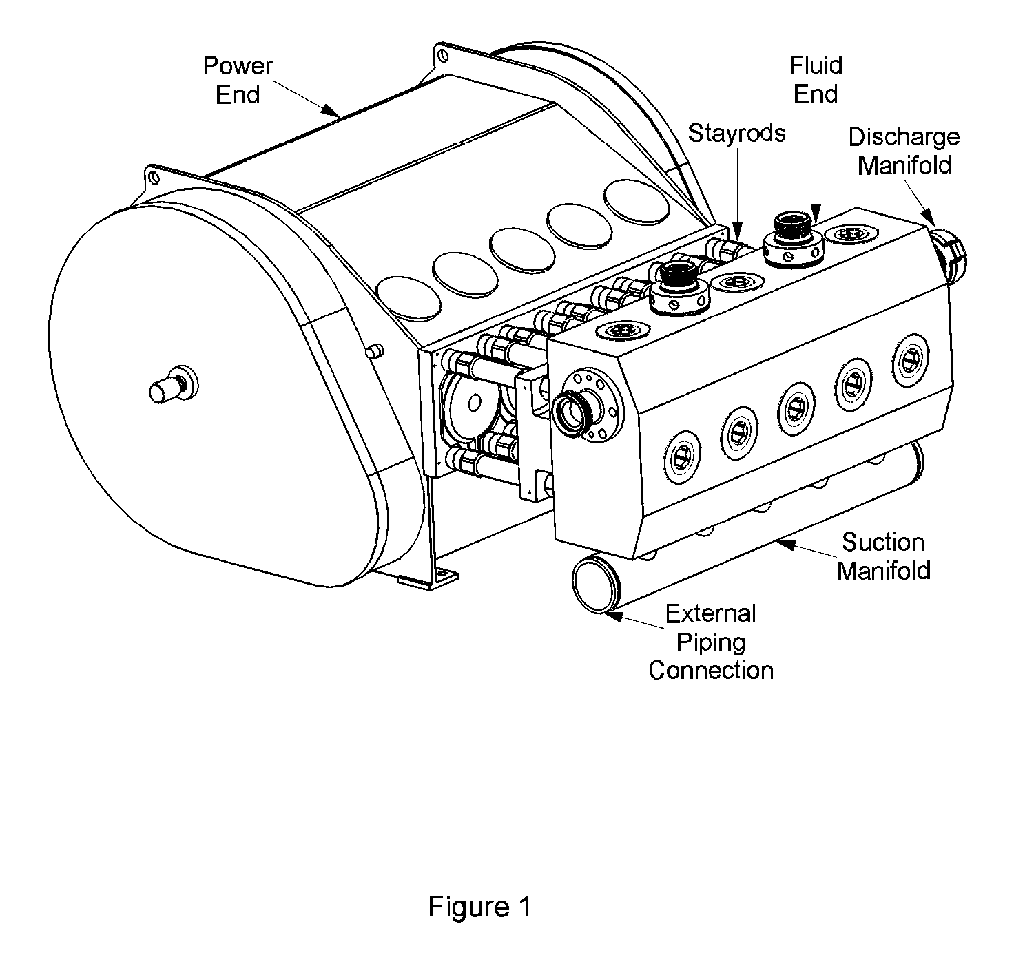
RELATED APPLICATION DATA[0001]This Patent Application claims priority to Provisional Patent Application No. 61 / 727,289, filed on Nov. 16, 2012, which, by this reference is incorporated for all purposes.FIELD OF THE INVENTION[0002]The invention generally concerns high-pressure plunger-type pumps useful, for example, in oil well hydraulic fracturing. More specifically, the invention relates to pump suction manifolds designed to properly feed suction valves utilized in rapid open-close cycling when pumping abrasive fluids, such as sand slurries at high pressures.BACKGROUND OF THE INVENTION[0003]Engineers typically design high-pressure oil field plunger pumps in two sections; the (proximal) power section and the (distal) fluid section which are connected by multiple stayrods. The power section, illustrated in FIG. 1, usually comprises a crankshaft, reduction gears, bearings, connecting rods, crossheads, crosshead extension rods, etc. Commonly used fluid sections usually comprise a plung...

Claims


Application Information

Patent Timeline
Patent Type & Authority Patents(United States)
IPC IPC(8): F04B53/16F04B23/06F04B9/109F04B53/10
CPCF04B53/16F04B9/1095F04B23/06F04B53/10Y10T137/86083
Inventor BLUME, GEORGE H
Owner ALTIS INVESTMENTS LLC
Why Eureka
Eureka Blog
Learn More