System and method for detecting and defeating a drone

a technology of drones and systems, applied in the direction of direction finders using radio waves, process and machine control, instruments, etc., can solve the problems of unparallel flexibility and convenience, and achieve the effects of reducing interference risk, speeding up the detection process, and high energy conversion efficiency

Active Publication Date: 2016-12-27
CELLANTENNA INT INC
View PDF62 Cites 118 Cited by
  • Summary
  • Abstract
  • Description
  • Claims
  • Application Information

AI Technical Summary

Benefits of technology

[0042]In at least one other preferred embodiment, an infrared camera can be mounted on a drone to detect other drones. This infrared camera mounted drone is configured to provide real time visual feed of the detected drone. As such, the visual of the detected drone via the mounted infrared camera would supplement the system to ascertain the make and model of the detected drone, thus enabling the system to speed up the process of detection by transmitting the overriding signal without any further ado. As such, in at least one of the preferred embodiments, the system is configured to detect the make and model of the detected drone.
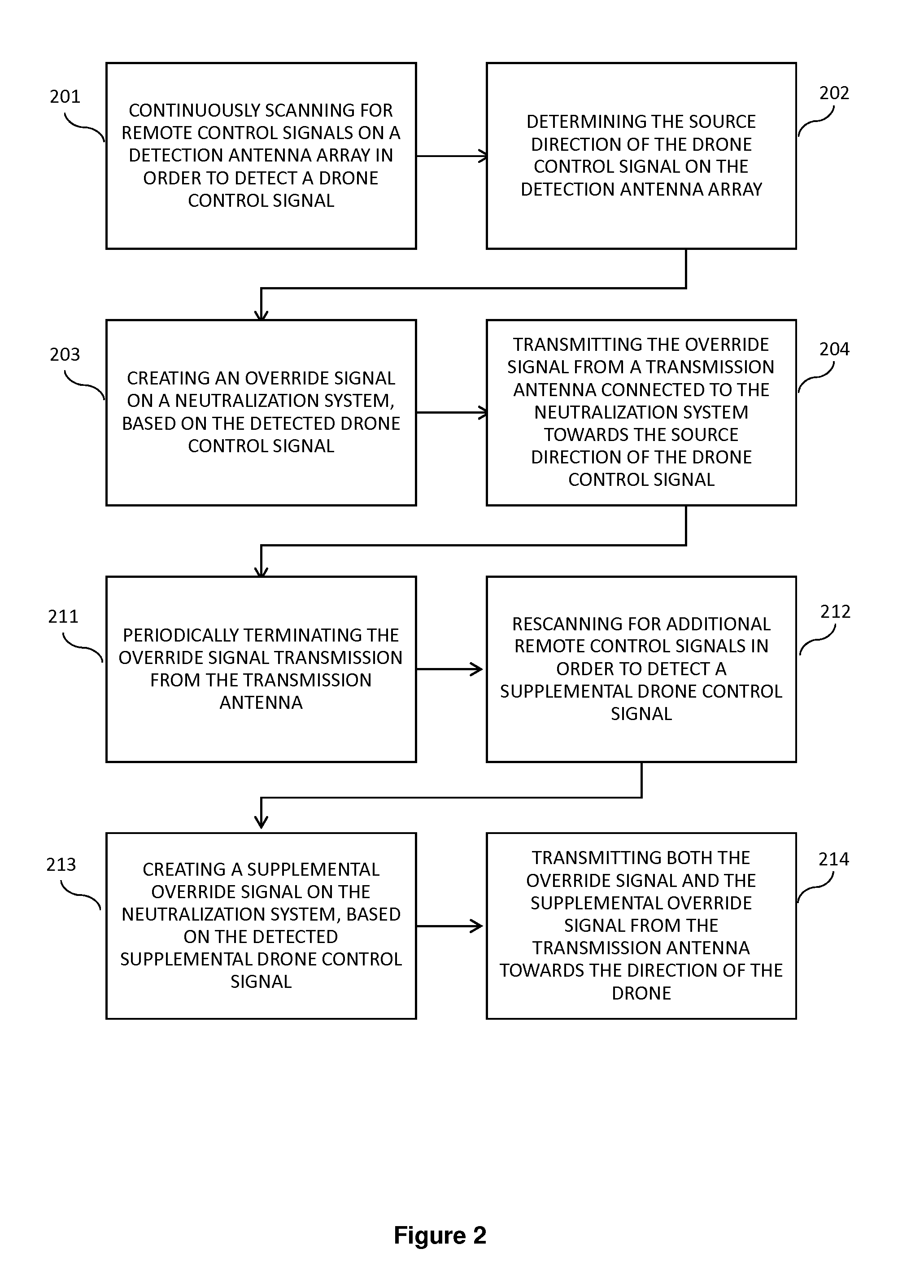
[0043]Looking even further, the method for detecting and defeating the drone according to at least one preferred embodiment comprises: continuously scanning for remote control signals on the detection antenna array in order to detect the drone control signal, determining the source direction of the drone control signal on detection antenna array, creating the override signal on the neutralization system based on the detected drone control signal and transmitting the override signal from the transmission antenna connected to the neutralization system towards the source direction of the drone control signal. These methods have been explained in great detail above. Given this, after transmitting the override signal from the transmission antenna towards the source direction, the detection antenna array detects the effect of the override signal transmitted from the transmission antenna on the drone. More specifically, the detection antenna array detects whether the override signal transmitted in the direction of the drone has effectively overridden the drone control signal, so as to render the drone uncontrollable from its source. As such, one of the preferred embodiments includes the override signal being operative on the drone, so as to override the existing drone control signal. So then, further measures pertaining to control and capture of the drone may proceed. No other alternate signals of higher frequency need to be transmitted. However, if the effect of the override signal is inoperative on the drone, at least one of the preferred embodiments includes proceeding with subsequent measures pertaining to transmitting stronger frequency based signals. More particularly

Problems solved by technology

The versatile combination of the sector antennas allows unparalleled flexib

Method used


Image

  • System and method for detecting and defeating a drone
  • System and method for detecting and defeating a drone
  • System and method for detecting and defeating a drone

Examples


Embodiment Construction

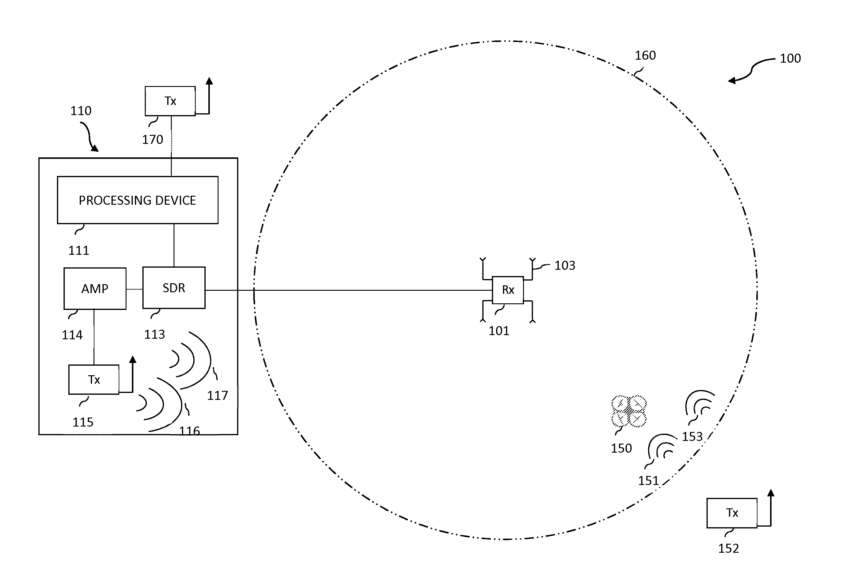
[0056]As shown in the accompanying drawings, the present invention is generally directed to a system and method for detecting and defeating a drone. More particularly, FIG. 1 illustrates a system 100 for detecting and defeating a drone 150. The system 100 generally includes a detection antenna array 101. The detection antenna array 101 generally is a set of two or more antennas and installed in various geometric arrays. In fact, in one of the preferred embodiments, the detection antenna array 101 includes a set of four 90-degree sector antennas 103. So then, each of the sector antennas 103 further comprises an antenna gain (not shown). The antenna gain is the ratio of the power required at the input of a loss-free reference antenna to the power supplied to the input of the given antenna to produce, in a given direction, the same field strength at the same distance. Given this, the antenna gain can be selected from a group of ranges in decibels (dB). The preferred ranges of the anten...


PUM


Abstract

The invention is directed to a system for detecting and defeating a drone. The system has a detection antenna array structured and configured to detect the drone and the drone control signal over a 360 degree field relative to the detection antenna array including detecting the directionality of the drone. The system also includes a neutralization system structured and configured in a communicating relation with the detection antenna array. The neutralization system has a transmission antenna structured to transmit an override signal aimed at the direction of the drone, an amplifier configured to boost the gain of the override signal to exceed the signal strength of the drone control signal, and a processing device configured to create and effect the transmission of the override signal. The invention is also directed to a method for detecting and defeating a drone.

Description

CLAIM OF PRIORITY[0001]The present application is based on and a claim of priority is made under 35 U.S.C. Section 119(e) to a provisional patent application that is currently in the U.S. Patent and Trademark Office, namely, that having Ser. No. 62 / 108,595 and a filing date of Jan. 28, 2015, and which is incorporated herein by reference.BACKGROUND OF THE INVENTION[0002]Field of the Invention[0003]This invention generally relates to systems and methods of detecting and defeating a drone. More specifically, a drone within the range of a detection antenna array is detected, its control signal is captured, and a neutralization system then emits an override signal based on the captured control signal.[0004]Description of Related Art[0005]The use of drones besides the United States military has increased exponentially in the recent years. In fact, the Federal Aviation Administration (“FAA”) expects that by year 2020, American skies will have up to 30,000 drones operating domestically, fue...

Claims


Application Information

Patent Timeline
IPC IPC(8): B64C39/02G01S3/02G05D1/00F41H13/00
CPCG05D1/0022G01S3/023B64C39/024F41H13/0093B64C2201/146G01S3/46H04K3/42H04K3/44H04K3/45H04K3/46H04K3/65H04K3/92H04K2203/14H04K2203/22H04K2203/32H04K3/94H04K3/60B64U2201/20
Inventor MELAMED, HOWARDMELAMED, STEVANSVANBERG, CHRISPONCE, MATIASHORVAT, MICHAEL
Owner CELLANTENNA INT INC
Why Eureka
Try Eureka