Oil-well-pump driving hydraulic system

a hydraulic system and oil well technology, applied in the direction of positive displacement liquid engines, servomotors, borehole/well accessories, etc., can solve the problem of difficult to ensure the pilot pressure of the operation piston to push the swash plate, and achieve the effect of simple piping, cost reduction, and cost saving

Active Publication Date: 2017-01-10
YUKEN KOGYO
View PDF13 Cites 0 Cited by
  • Summary
  • Abstract
  • Description
  • Claims
  • Application Information

AI Technical Summary

Benefits of technology

[0015]In the oil-well-pump driving hydraulic system of the present invention, a method in which the piston pump waits in the unloaded state by mechanically cutting off the supplied pressure of the external pilot and returning to an autogenous pressure pump even when the controller stops for a certain reason and the load of the piston pump is lost is achieved as the compact and cost-effective structure containing the cut-off system in the pump body. Thus, there is an advantageous effect that simple piping and cost reduction can be achieved even in the external pilot hydraulic circuit.

Problems solved by technology

In such an autogenous pressure control piston pump, when the discharge pressure becomes a pump minimum regulation pressure or below, it becomes difficult to ensure a pilot pressure for the operation piston to push the swash plate.

Method used


Image

  • Oil-well-pump driving hydraulic system
  • Oil-well-pump driving hydraulic system
  • Oil-well-pump driving hydraulic system

Examples


example

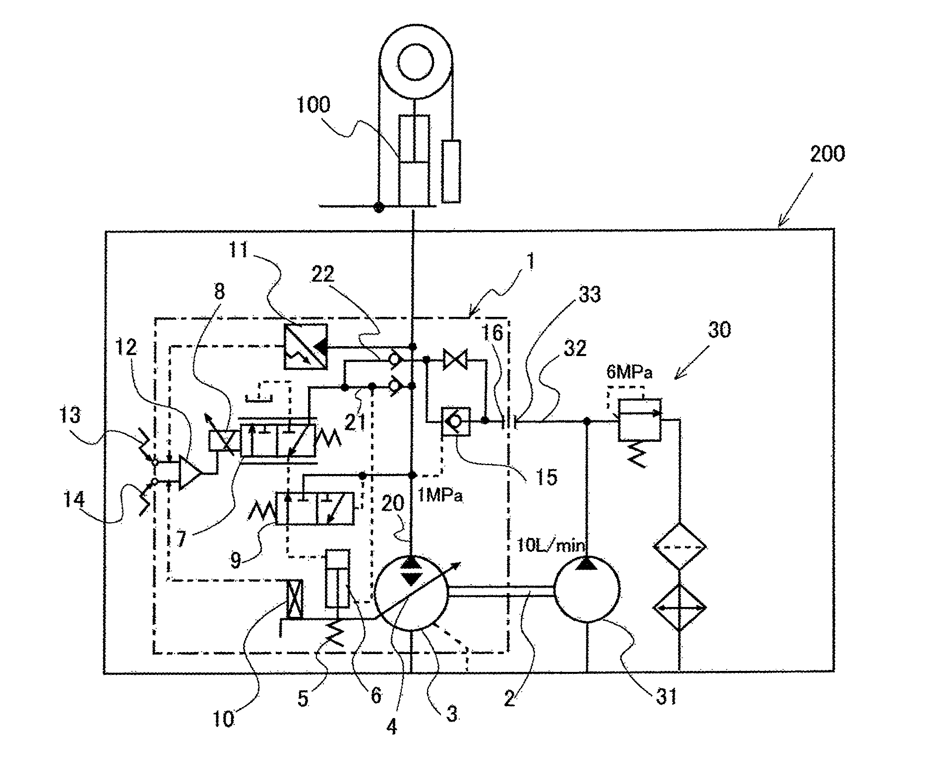
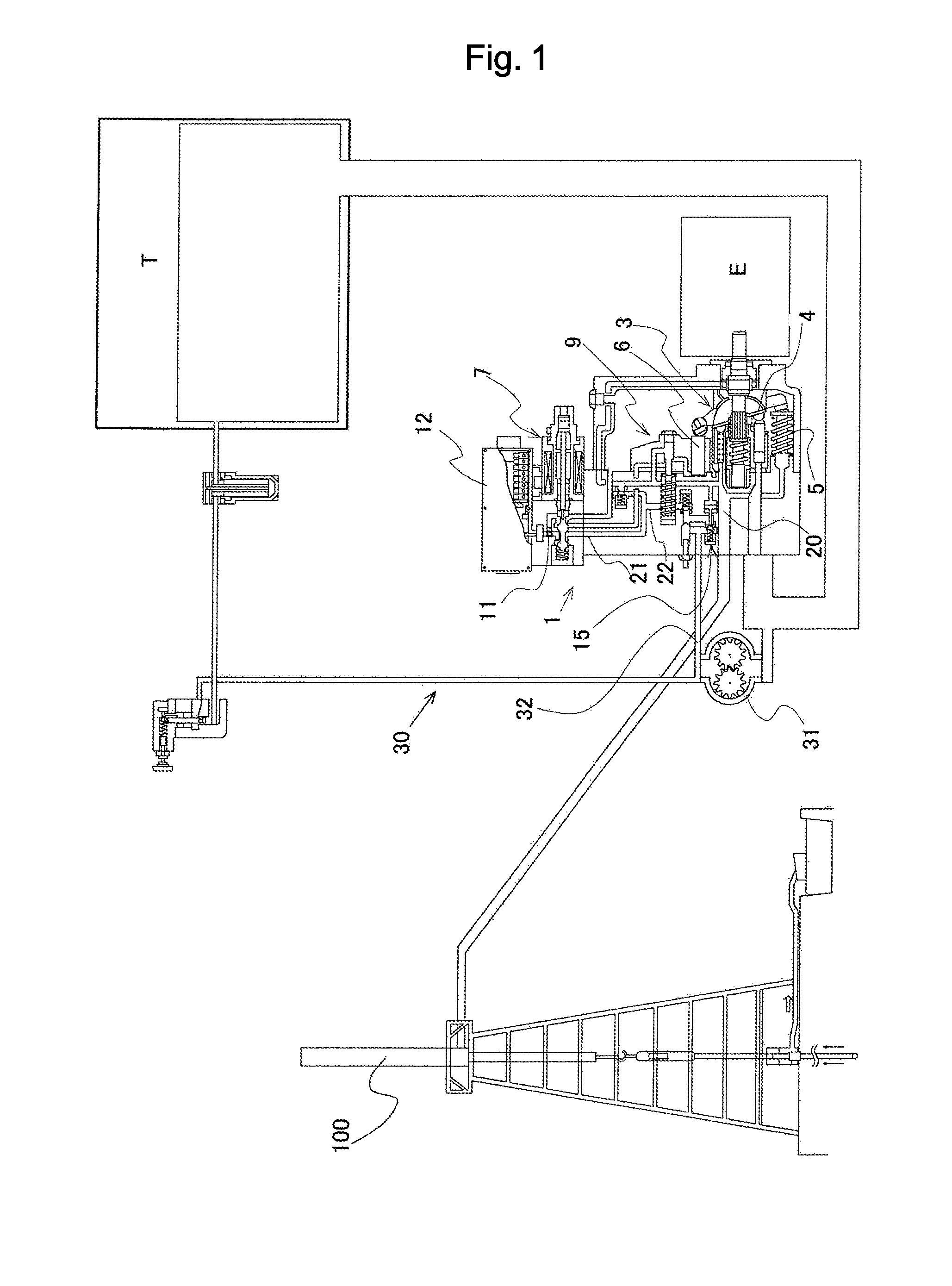
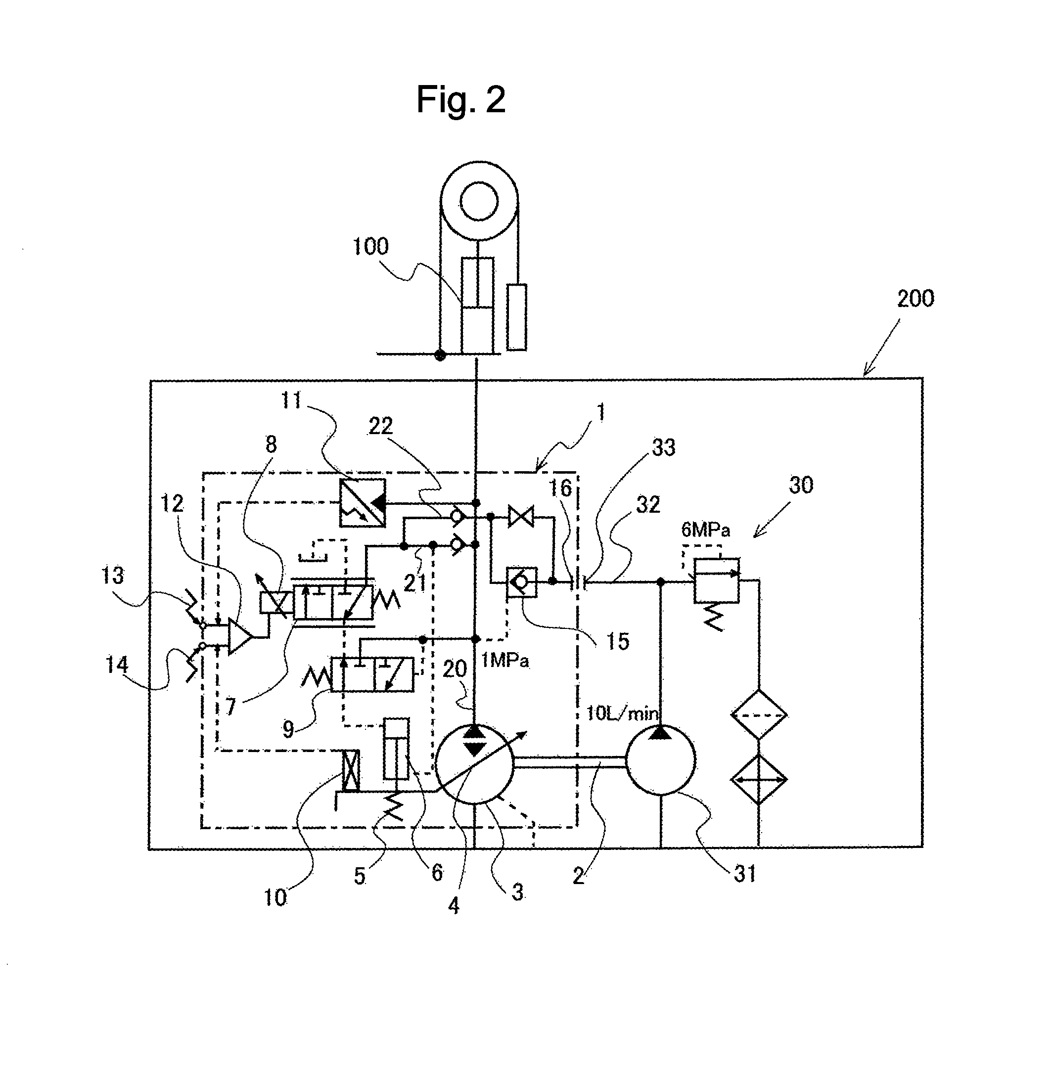
[0036]A structure of an oil-well-pump driving hydraulic system as one example of the present invention is shown in a schematic cross section view of FIG. 1 and a schematic view of a hydraulic circuit of FIG. 2. The hydraulic system of this embodiment includes a pump body 1 that supplies hydraulic fluid to a hydraulic cylinder 100, which is a drive portion of the oil well pump, and an external pilot hydraulic circuit 30 connected to the pump body 1. In this embodiment, as a pump component in the pump body 1, an axial type bidirectional variable displacement piston pump is provided to control a discharge rate in response to an angle of a swash plate.

[0037]The pump body 1 has a compact form in which components are assembled as a single unit structure in the same housing, and is connected to the external pilot hydraulic circuit 30 at a connection portion 16 formed in the side surface of the housing.

[0038]Namely, the pump body 1 integrally contains: a bidirectional variable displacement ...


PUM


Abstract

In an oil-well-pump driving hydraulic system capable of avoiding occurrence of cavitation, at least a bidirectional variable displacement piston pump, a discharge rate detection portion, a discharge pressure detection portion, and a proportional solenoid control valve are contained as a single unit structure in a same housing as a pump body. The pump body includes: a connection portion provided on a side surface of the housing and to which a pump discharge passage of an external pilot hydraulic circuit is connected; and a second pilot passage that introduces an external pilot pressure from the connection portion to a pilot passage between the discharge passage of the piston pump and the proportional solenoid control valve.

Description

FIELD OF THE INVENTION[0001]The present invention relates to a hydraulic system in which a bidirectional proportional solenoid piston pump for driving an oil well pump is structured using an external pilot method.BACKGROUND OF THE INVENTION[0002]When reservoir pressure is low in oil wells and crude oil does not flow, it is pumped for oil production. The sucker rod pump having a simple structure as shown in FIG. 8 has been used widely for many years particularly as an oil production pump method on land. This is driven by transmitting reciprocation of a reciprocating apparatus placed on the ground to the pump plunger connected to the head of a sucker rod R at the pipe bottom via this rod R.[0003]Also in such an old pump method, for example by improving the control system of the pump jack, high speed operation is made possible to achieve high efficiency (for example, see Patent Document 1). However, in recent years, in renewal of oil well pump systems due to obsolescence, transitions t...

Claims


Application Information

Patent Timeline
Patent Type & Authority Patents(United States)
IPC IPC(8): F04B49/00F04B49/22F04B47/04F15B11/042E21B43/12F04B49/10F04B47/02F04B49/06F04B49/08F04B49/03
CPCF04B49/22F15B11/0423F04B49/06E21B43/127F04B47/02F04B47/04F04B49/106F04B49/002F04B49/03F04B49/08F15B2211/20553
Inventor HIRAIDE, HIROKAZUHAYASHI, AKIHIRO
Owner YUKEN KOGYO
Why Eureka
Try Eureka