
Scroll structure of centrifugal compressor

a centrifugal compressor and scroll technology, applied in the direction of machines/engines, stators, liquid fuel engines, etc., can solve the problems of pressure loss, pressure loss, following pressure loss inside the scroll, etc., to prevent secondary flow loss, reduce flow area, and reduce the effect of recirculation

Active Publication Date: 2017-01-10
MITSUBISHI HEAVY IND LTD
View PDF27 Cites 8 Cited by
  • Summary
  • Abstract
  • Description
  • Claims
  • Application Information

AI Technical Summary

Benefits of technology

[0017]The present invention was made in view of these problems. It is an object of the invention to provide a scroll structure of a centrifugal compressor having an improved scroll cross-sectional shape near the tongue portion to minimize flow recirculation from the outlet passage of the diffuser 11 into the scroll passage 13 near the tongue portion, so as to improve the compressor performance at a low flow-rate operating point as well as the anti-surge performance.

Problems solved by technology

This phenomenon causes the following pressure losses inside the scroll.
(1) First is a pressure loss caused by flow separation.
(2) Second is a pressure loss caused by friction.
This increases the pressure loss by friction inside the scroll passage.
It then follows that flow recirculation that occurs in the tongue portion is the major cause of pressure loss inside the scroll at a low flow-rate operating point.
However, it does not disclose how to minimize the amount of recirculation near the tongue portion for better machine performance.
Patent Document 2 shows reducing the negative pressure region near the tongue portion, but it relates to improvement by means of a diffuser and does not disclose improvement of the scroll cross-sectional shape for better machine performance.

Method used


Image

  • Scroll structure of centrifugal compressor
  • Scroll structure of centrifugal compressor
  • Scroll structure of centrifugal compressor

Examples


first embodiment

[0047](First Embodiment)

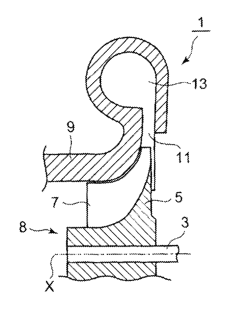
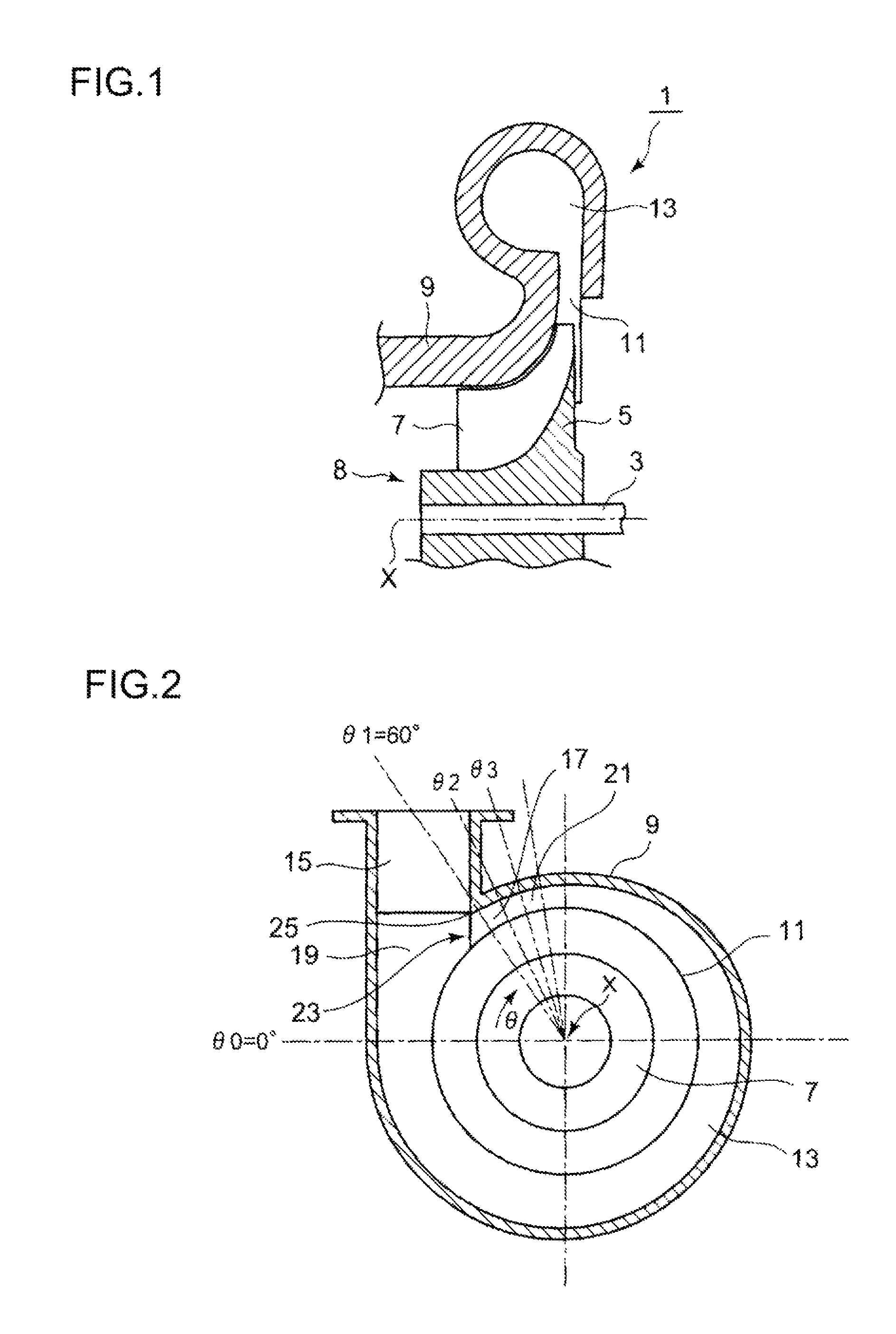
[0048]FIG. 1 shows a schematic cross-sectional view of a centrifugal compressor 1 of the present invention. The centrifugal compressor 1 shown in this embodiment is applied to a turbocharger. A plurality of compressor blades 7 are formed on the surface of a hub 5 secured to a rotating shaft 3 driven by a turbine (not shown), with a compressor housing 9 covering the outside of the compressor blades 7. A diffuser 11 is formed on the radially outer side of the compressor blades 7, and a scroll passage 13 is formed around this diffuser 11.

[0049]FIG. 2 shows a cross section of the scroll passage 13. The compressor housing 9 includes the scroll passage 13 and a linear outlet passage 15 that communicates with the scroll passage 13. The cross-sectional area of the scroll passage 13 increases with an increase in spiral angle θ clockwise in FIG. 2 from the scroll start 17, and with spiral angle θ□□ exceeding 360°, the scroll reaches a scroll end 19. The scroll passage ...

second embodiment

[0070](Second Embodiment)

[0071]Next, a second embodiment will be described with reference to FIG. 4.

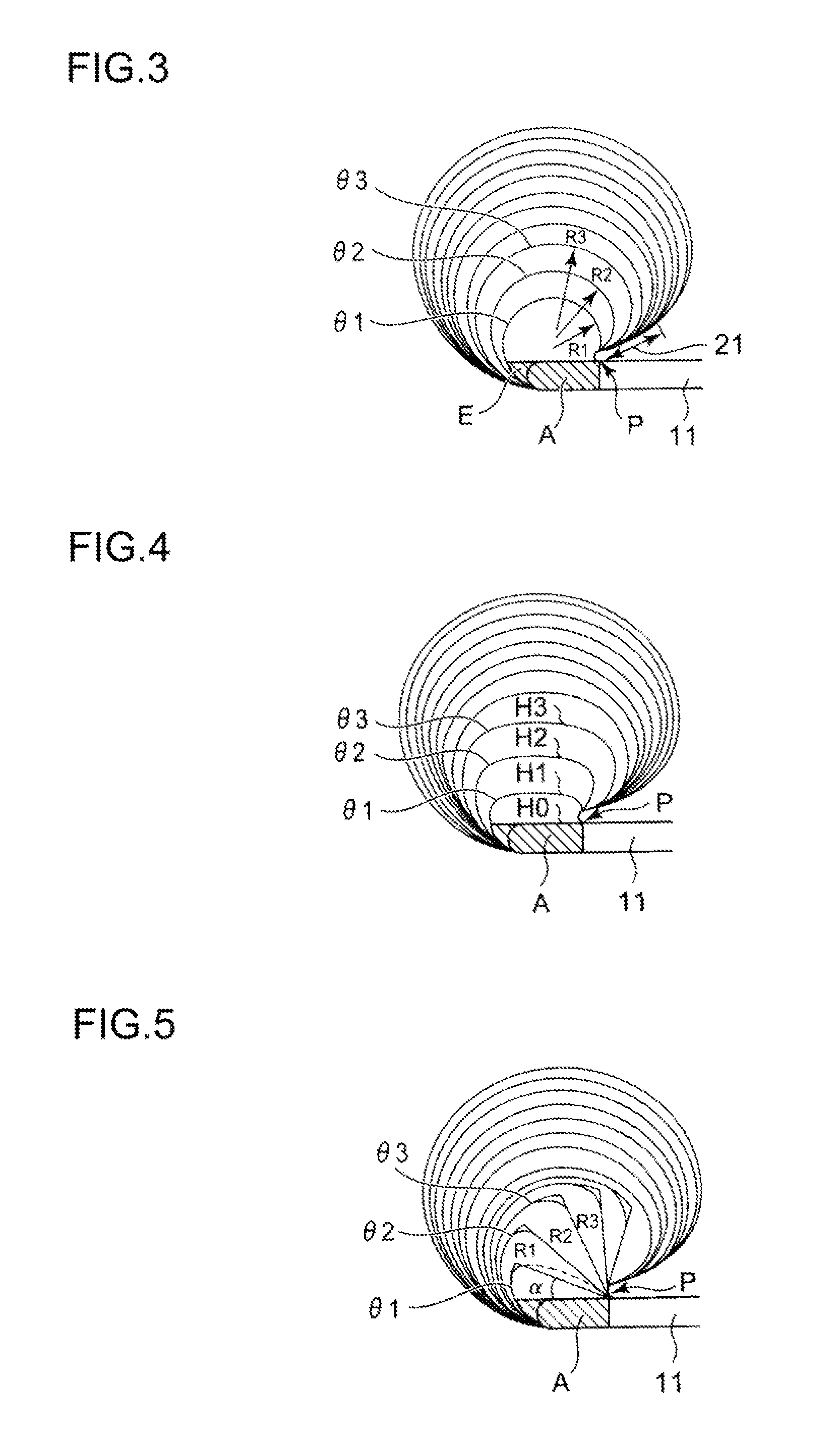
[0072]The characteristic feature here is that in the transformation of the cross-sectional shape of the flat connecting portion A into the circular shape at the transition part 21, a flat portion H is provided to part of the cross-sectional shape on the downstream side as shown in FIG. 4, this flat portion H gradually decreasing in the transformation into the circular shape.

[0073]In the first embodiment described above, the flat shape of the flat connecting portion A changes immediately into a small circular shape, after which the diameter of the circular shape increases gradually from R1. In the second embodiment, the flat portion H is provided in this transformation, wherein the flat portion H is decreased so that the shape gradually becomes circular.

[0074]More specifically, the passage has the flat connecting portion A at the position of the tongue 25 in FIG. 4, where the spiral an...

third embodiment

[0077](Third Embodiment)

[0078]Next, a third embodiment will be described with reference to FIG. 5.

[0079]In the first embodiment described above, the cross-sectional shape was gradually enlarged from a small circle, and in the second embodiment, the cross-sectional shape was gradually enlarged from a flat shape. In the third embodiment, the shape is changed in accordance with, or in conformity with the flow coming out of the diffuser 11 near the flow passage joint 23.

[0080]Near the flow passage joint 23, the flow coming out of the diffuser 11 does not exist all across the cross section of the scroll but flows closer to the outer circumference of the scroll in a spiraling motion inside the scroll.

[0081]Therefore, in the transition part 21, the flat shape of the flat connecting portion A is changed into a circular shape such that, while one flat surface of the flat shape having the same height as that of the diffuser 11 is matched with one surface in the height direction of the diffuse...


PUM


Abstract

A scroll structure of a centrifugal compressor 1 having a spirally formed scroll passage 13. The scroll passage 13 includes: a flat connecting portion A at a flow passage joint 23 where a scroll start and a scroll end of the scroll passage 13 meet, this flat connecting portion having a flat cross-sectional shape with a same height as that of an outlet passage of a diffuser; and a transition part 21 where the flat cross-sectional shape of the flat connecting portion A gradually changes back to a circular cross-sectional shape along a circumferential direction.

Description

TECHNICAL FIELD[0001]The present invention relates to a scroll structure (spiral chamber structure) of a centrifugal compressor used in turbochargers or the like of vehicles or ships.BACKGROUND ART[0002]Centrifugal compressors used in a compressor part or the like of turbochargers in vehicles or ships give a kinetic energy to a fluid through rotation of a vaned wheel and discharge the fluid radially outward to raise the fluid pressure by the centrifugal force.[0003]Various improvements have been made to the scroll structure of the centrifugal compressor in response to the demands for a high pressure ratio and high efficiency in a wide operation range.[0004]Patent Document 1 (Japanese Patent Publication No. 4492045), for example, shows one example of conventional techniques, represented by a centrifugal compressor having a casing with a spirally formed scroll passage. The width in the axial direction of the scroll passage is gradually increased radially from inside to outside, the wi...

Claims


Application Information

Patent Timeline
Patent Type & Authority Patents(United States)
IPC IPC(8): F04D29/40F04D29/42F04D29/44
CPCF04D29/403F04D29/4206F04D29/441F05D2250/52
Inventor IWAKIRI, KENICHIROTOMITA, ISAOEBISU, MOTOKISUZUKI, HIROSHISHIRAISHI, TAKASHI
Owner MITSUBISHI HEAVY IND LTD
Learn More