Modular securing device for ROV and diver mate-able subsea applications

a technology of securing device and subsea equipment, which is applied in the direction of rod connection, borehole/well accessories, instruments, etc., can solve the problems of insufficient sealing and cleanliness to provide desired reliability, ineffective spring/piston concept for sealing electrical connectors, and inability to meet the requirements of subsea equipment functions and operational requirements, etc., to achieve quick, reliable and low-cost, positive meta-centric height, and neutralizing the buoyancy force

Inactive Publication Date: 2017-01-24
TELEDYNE INSTR INC
View PDF12 Cites 1 Cited by
  • Summary
  • Abstract
  • Description
  • Claims
  • Application Information

AI Technical Summary

Benefits of technology

[0023]The present invention comprises a modular and versatile mechanical design that provides a quick, reliable and low-cost solution to secure immersed, un-restrained objects in seawater or freshwater with vertical stability and a positive meta-centric height to a fixed structure, neutralizing the buoyancy force effect. The present invention also reduces the risk of mating and / or de-mating connectors and reduces the probability of misalignments which may result in unreliable and costly failures for the subsea applications.
[0024]The present invention provides a T-handle locking key and T-handle ACME threaded shaft / stud assembly for securing an MCDU and removable parking plate to an MCDU landing unit. Use of the quick disconnect T-handle locking key and threaded T-handle body and stud assemblies for attaching an MCDU to an MCDU landing frame provides the benefit of easy and quick removal or replacement of an MCDU or parking plate. The modular securing devices may be operated either manually by a diver or remotely by an ROV. The modular securing devices according to the present invention may also be used in other configurations and with other frames, structures, or devices as a method of securing one apparatus to another in a sub-sea environment.

Problems solved by technology

Functional and operational requirements of subsea equipment have become increasingly complex along with the sensing and monitoring equipment and control systems used to insure proper operation.
Problems with this design included that sealing and cleanliness were not adequate to provide desired reliability.
The spring / piston concept used for sealing electrical connectors is not effective for optical connectors as pistons get in the way of the light path.
There was no attempt to exclude sand or silt from the interfaces, and the resulting performance was left to chance.
Such devices are often referred to as “wet-mate” devices and often are at such great depths that temperature and other environmental factors present extreme conditions for materials used in such devices.
One major problem in designing such pressure compensated or pressure balanced units is the performance and longevity of seals required to exclude seawater and / or contaminates from the contact chamber after repeated mating and de-mating.
However, this type of arrangement cannot be used in a straightforward way for an optical connector since the optical contacts must be able to engage axially for practical purposes.
Other known fiber-optic connectors have similar seals which are not suitable for use under some conditions and may tend to lose effectiveness after repeated mating and de-mating.
These overcome some of the reliability problems of penetrable seals, for example, but can be too complex for miniaturized connectors.
Most existing wet-mate connectors of the pressure compensation-type depend on elastomers, which have several known disadvantages and which only grow as required temperature and pressure performance in the operating environments increase.
Above 350° F. in particular, but at lower temperatures as well, elastomers in seawater degrade rapidly, and can fail due to numerous causes, including: rupture; rapid gas decompression (RGD) embolisms; leakage; melting; and gas permeation.
Other pressure compensation systems typically rely on metal bellows, which have different weaknesses.
At the scale of ever-smaller optical feedthrough systems, where diameters of compensation systems are typically less than an inch, the metal of the bellows are extraordinarily thin, and the welded joints may be subject to fatigue, opening up failure pathways similar to those of elastomers.
Operators experience signal loss on gas and gas-lift wells during start up and shutdown.
In addition, pressure compensated systems in gaseous environments have experienced complete loss of pressure compensation and infiltration of seawater into spaces that should be dielectrically insulated by oil.
One major problem in designing such units is the provision of seals which will adequately exclude or evacuate seawater and / or contaminants from the contact chamber after repeated mating and de-mating operations.
However, in normal applications, MCDUs may need to be removed for refurbishment or repair after only 5-8 years as a result of factors including galvanic corrosion.
Furthermore, MCDUs and other sub-sea devices may need to be moved from their original location or removed entirely due to factors other than equipment failure.
For example, a planned oil well may not be economically feasible due to the oil reserve not being as large as originally surveyed.
Sub-sea mining equipment also may require more power than sub-sea oil drilling equipment and may therefore put additional strain on equipment such as MCDUs, requiring more frequent refurbishment or repair.
Typically, when an MCDU needs to be replaced or removed, removal is difficult because of the buildup of silt and other particulates and because of galvanic corrosion.
These and other factors may make it hard if not impossible to remove an MCDU from its landing frame, resulting in the inability to remove, reuse, or refurbish either the frame or the MCDU.
Refurbishing an MCDU is economically desirable over replacing and MCDU due to the very high equipment cost per MCDU.
Additionally, when connecting various wet-mate type connectors to or from an MCDU, problems exist in securing connectors, cables, remote operate vehicles (ROVs), and other materials.
Currently there exists no method for securing immersed, un-restrained objects in seawater or freshwater with vertical stability and a positive meta-centric height to a fixed structure, neutralizing the buoyancy force effect.

Method used


Image

  • Modular securing device for ROV and diver mate-able subsea applications
  • Modular securing device for ROV and diver mate-able subsea applications
  • Modular securing device for ROV and diver mate-able subsea applications

Examples


Embodiment Construction

[0047]The present invention and system will now be described in more detail with reference to exemplary embodiments as shown in the accompanying drawings. While the present invention and system is described herein with reference to the exemplary embodiments, it should be understood that the present invention and system is not limited to such exemplary embodiments. Those possessing ordinary skill in the art and having access to the teachings herein will recognize additional implementations, modifications, and embodiments as well as other applications for use of the invention and system, which are fully contemplated herein as within the scope of the present invention and system as disclosed and claimed herein, and with respect to which the present invention and system could be of significant utility.

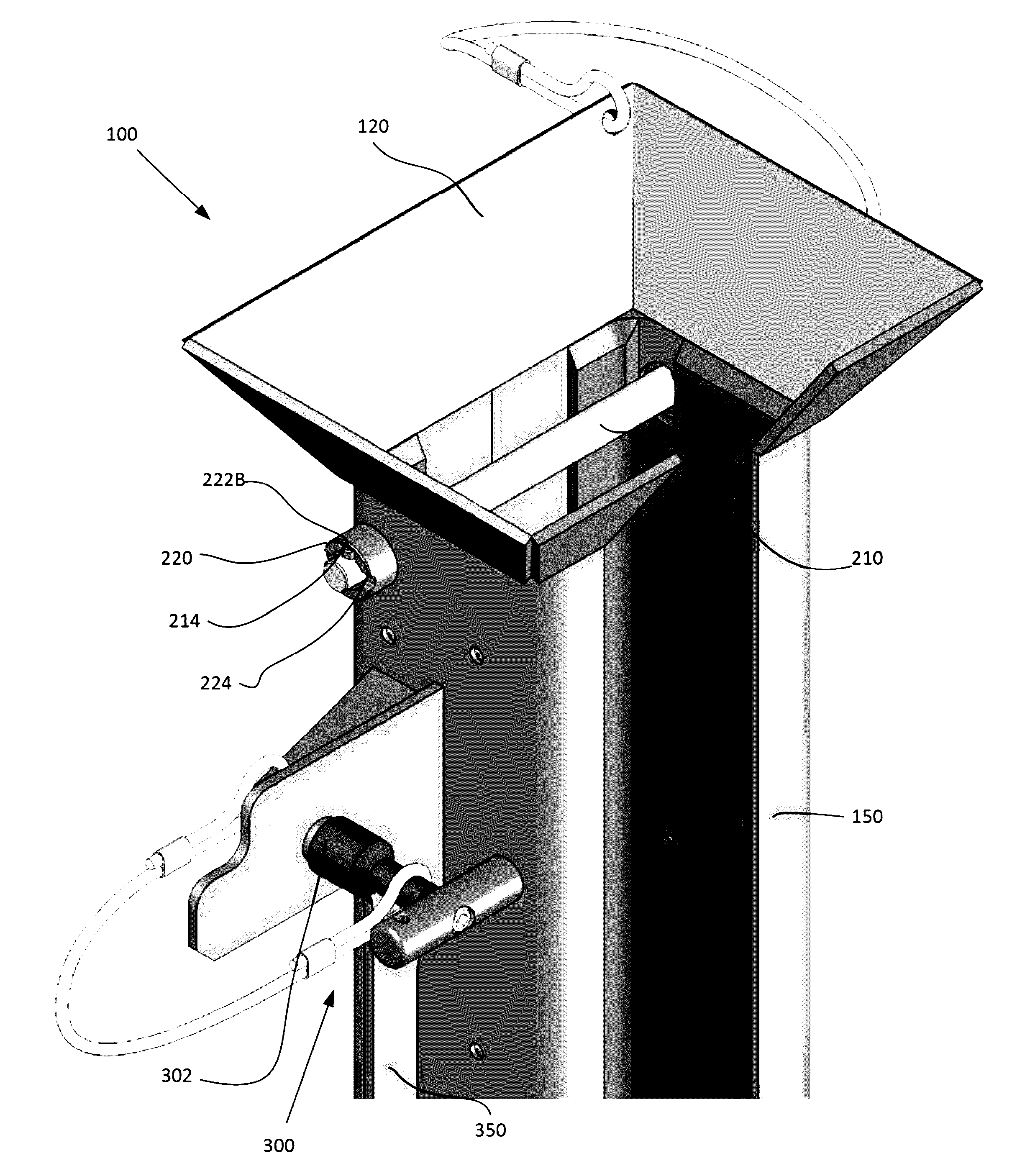
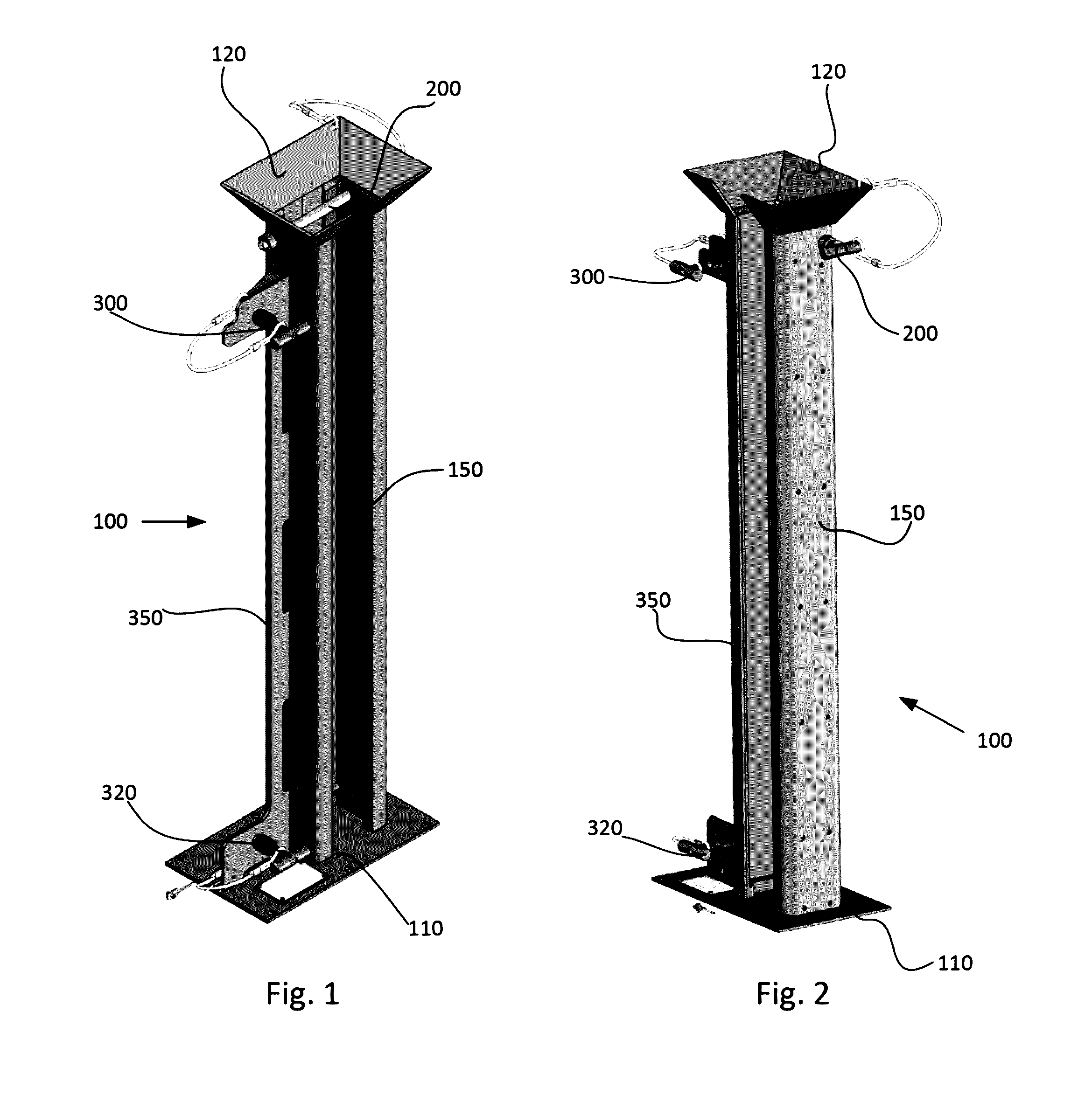
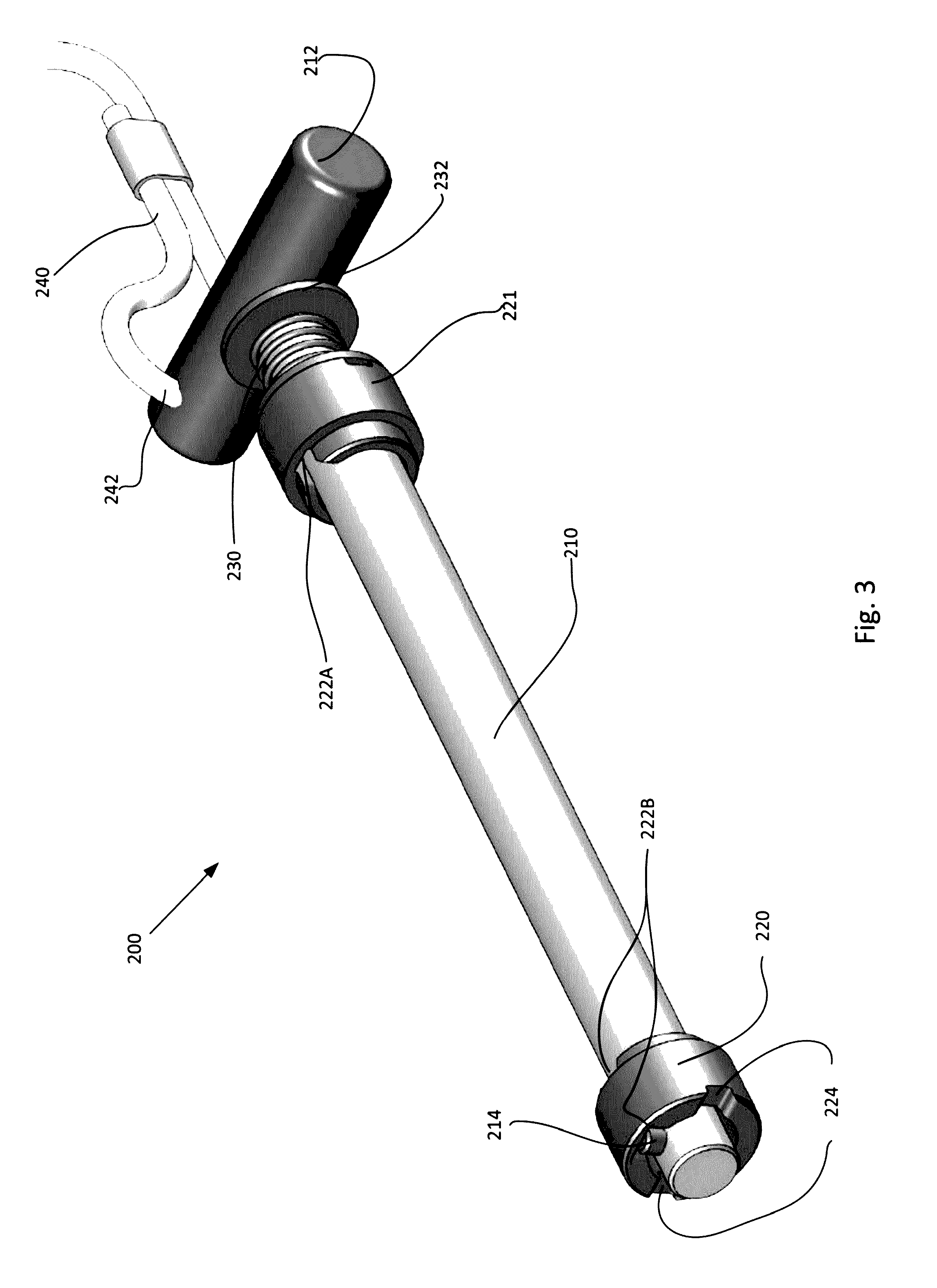
[0048]Certain embodiments as disclosed herein provide for a modular securing device for ROV and diver mate-able subsea applications in which a single T-handle locking key is attached to th...


PUM


Abstract

The present invention relates generally to a modular locking and retaining mechanical design solution to reliably secure immersed, unrestrained and un-powered objects in a fluid environment to a fixed support surface such as a mounting frame or panel, with a quick connect / disconnect engagement method by a diver (i.e. manual mate) or remote-operated vehicles (ROVs) mate, into a fixed mounting frame or panel installed at a subsea deployed platform for oil and gas offshore applications.

Description

FIELD OF THE INVENTION[0001]The present invention relates generally to a modular locking and retaining mechanical design solution to reliably secure immersed, unrestrained and un-powered objects in a fluid environment to a fixed support surface such as a mounting frame or panel, with a quick connect / disconnect engagement method by a diver (i.e. manual mate) or remote-operated vehicles (ROVs) mate, into a fixed mounting frame or panel installed at a subsea deployed platform for oil and gas offshore applications.BACKGROUND OF THE INVENTION[0002]In offshore drilling and production operations, equipment are often subjected to harsh conditions thousands of feet under the sea surface with working temperatures of −50° F. to 350° F. with pressures of up to 15,000 psi. Subsea control and monitoring equipment commonly are used in connection with operations concerning the flow of fluid, typically oil or gas, out of a well. Flow lines are connected between subsea wells and production facilities...

Claims


Application Information

Patent Timeline
Patent Type & Authority Patents(United States)
IPC IPC(8): E21B41/00F16B7/20F16B21/04
CPCE21B41/0007F16B7/20F16B21/04G02B6/3898G02B6/3816F16M13/02G02B6/4416G02B6/4427H02G9/02H02G9/10
Inventor GONZALEZ, JOSE RAULBARTELL, MATTHEW CHRISTOPHER
Owner TELEDYNE INSTR INC
Why Eureka
Try Eureka