
Cable for radio frequency communication

a radio frequency communication and cable technology, applied in the field of near field communication systems, can solve the problems of electrical contacts corroding, copper cables are common, and cannot support high-bandwidth (>1 gbps) applications such as hd video, and achieve low power consumption, high data-rate connectivity, and short range

Active Publication Date: 2017-02-07
CORNING INC
View PDF25 Cites 1 Cited by
  • Summary
  • Abstract
  • Description
  • Claims
  • Application Information

AI Technical Summary

Benefits of technology

The patent describes a communication system that delivers high data-rate connectivity to a client device through a very short range wireless connection. The system is tolerant of contamination and misalignment and has either a very low power draw or can serve to charge the client device. The link formed by the communications cable and the host and / or client devices is shielded from external electromagnetic interference, resulting in secure wireless links at both ends. The cable utilizes the full 7 GHz spectrum and is compatible with all wireless systems operating in the (60 GHz band. The short wireless coupling ranges and EM shielding eliminate the possibility of multi-path effects, leading to low power consumption and simplified required digital signal processing in the transceivers.

Problems solved by technology

Connections via copper cables are common, but may not support high-bandwidth (>1 Gbps) applications such as HD video.
In addition, electrical contacts can corrode and electrical conduction can become unreliable.
Mating receptacles are also susceptible to contamination and damage and provide an opening into the portable device package for possible ingress of contaminants and moisture.
On the other hand, optical data communications technologies can achieve high data rates, but the optical connections can be easily impaired by contamination.

Method used


Image

  • Cable for radio frequency communication
  • Cable for radio frequency communication
  • Cable for radio frequency communication

Examples


Embodiment Construction

[0058]In the following detailed description, for purposes of explanation and not limitation, example embodiments disclosing specific details are set forth to provide a thorough understanding of the present disclosure. However, it will be apparent to one having ordinary skill in the art, having had the benefit of the present disclosure that embodiments disclosed herein may be practiced in part or in whole within still other embodiments that depart from the specific details disclosed herein. Moreover, descriptions of well-known devices, methods and materials may be omitted so as not to obscure the present description. Finally, wherever applicable, like reference numerals refer to like elements.

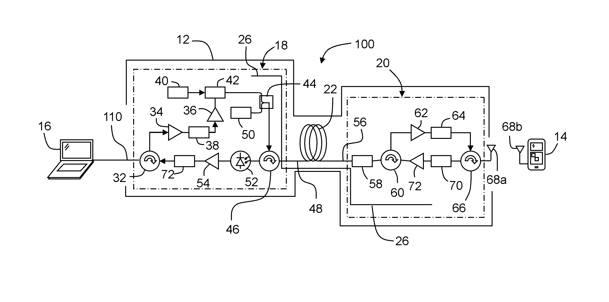
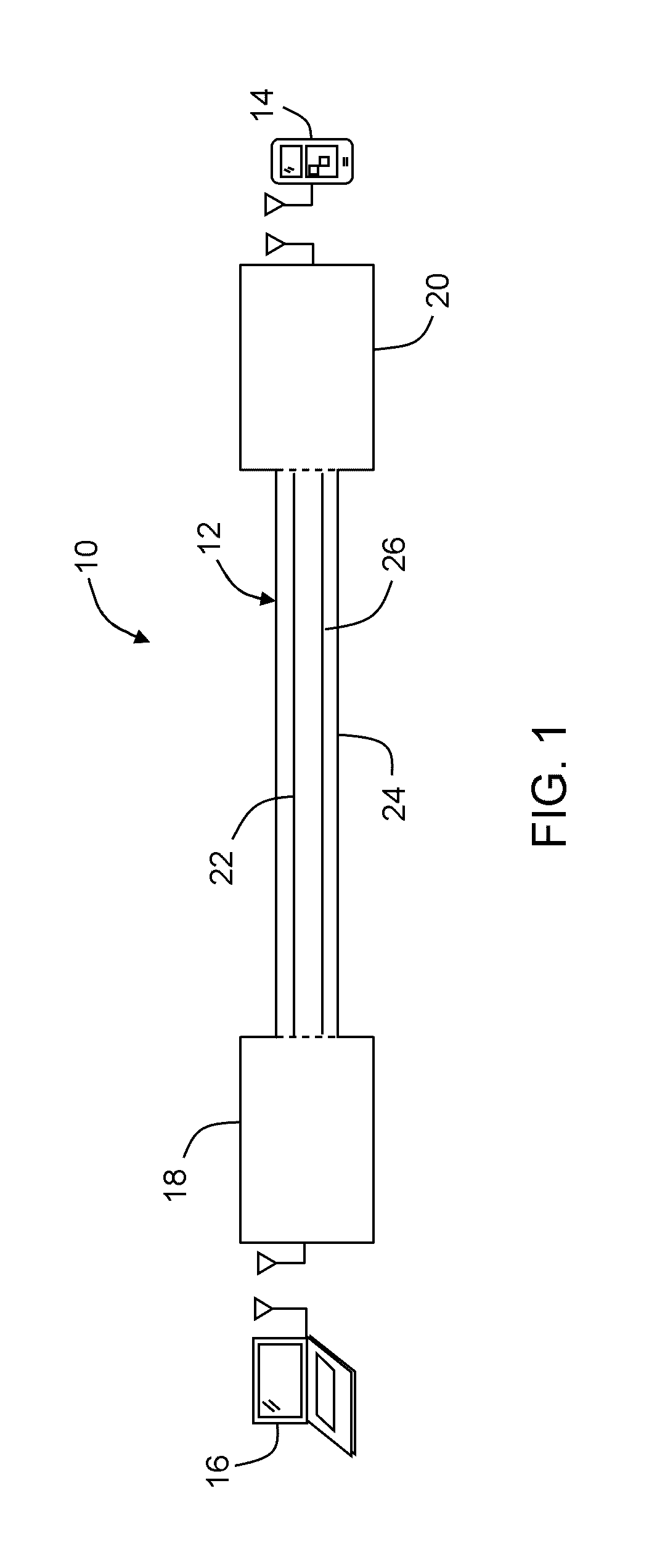
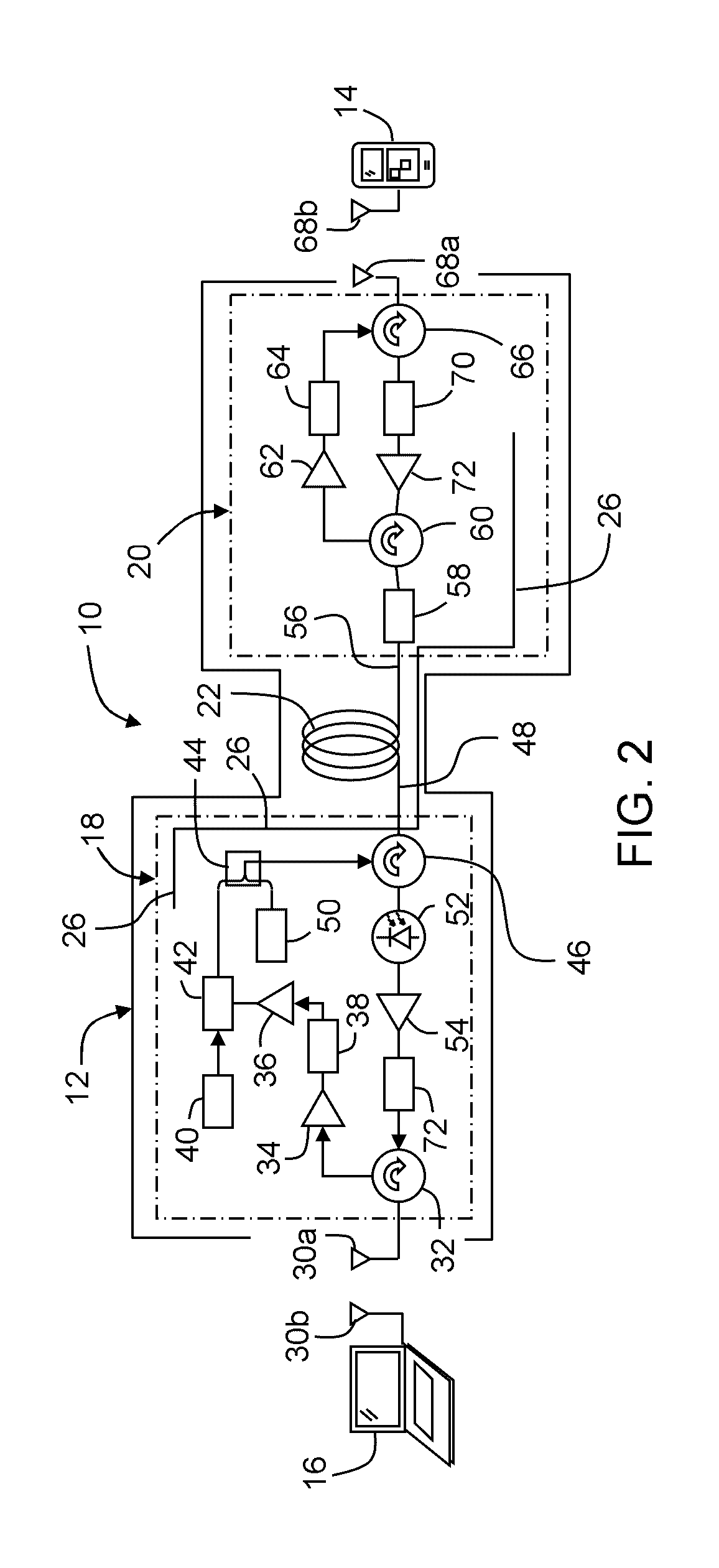
[0059]Shown in FIG. 1 is an embodiment of a high data-rate wireless radio frequency (RF) communication system 10. While radio frequencies can extend over broad frequency ranges, as used herein RF is intended to mean within a frequency range generally extending between about 1 GHz and about 100 G...


PUM


Abstract

A fiber-optic based communication system for facilitating communication between a client device, such as a hand-held computing device, and a host device, such as a desktop computer, a lap-top computer, a tablet device or any other computing device. The communication system includes a cable comprising electronic devices positioned at terminal ends of an optical fiber that provides for communication between the client device and the host device, and the communication occurs via electromagnetic coupling in the near field at at least one end of the cable.

Description

PRIORITY APPLICATIONS[0001]This application is a continuation of International Application No. PCT / US13 / 48107, filed on Jun. 27, 2013, which claims the benefit of priority to U.S. Application No. 61 / 667,162, filed on Jul. 2, 2012, both applications being incorporated herein by reference.BACKGROUND[0002]Field[0003]The present disclosure relates to a near field communication system for connecting a client electronic device to a host electronic device, and more particularly wherein the near field communication system includes a fiber-optic based cable comprising at least one active electronic device positioned at a terminal end of the cable configured for near field communication with the client device.[0004]Technical Background[0005]Conventional communication between client devices such as cell phones and a host device such as a personal computer have utilized direct electrical contact between the devices. For example, a universal serial bus (USB) cable is plugged at one terminal end ...

Claims


Application Information

Patent Timeline
Patent Type & Authority Patents(United States)
IPC IPC(8): H04B10/2575
CPCH04B10/25759H04B10/25758
Inventor BENJAMIN, SELDON DAVIDFORTUSINI, DAVIDE DOMENICONG'OMA, ANTHONYGEORGE, JACOB
Owner CORNING INC
Learn More