Treatment of release layer

a technology of release layer and release layer, which is applied in the direction of printing, duplicating/marking methods, and other printing apparatus, can solve the problems of direct ink jetting of liquid inks, aqueous, and process drawbacks, and achieve the effect of improving the quality of liquid inks, reducing the risk of contamination, and reducing the safety and environmental concerns

Active Publication Date: 2017-02-14
LANDA
View PDF19 Cites 24 Cited by
  • Summary
  • Abstract
  • Description
  • Claims
  • Application Information

AI Technical Summary

Benefits of technology

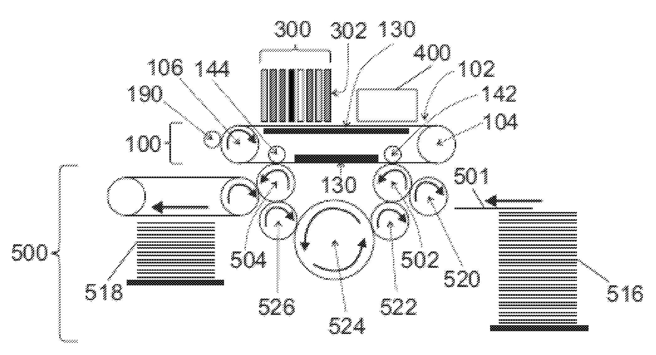
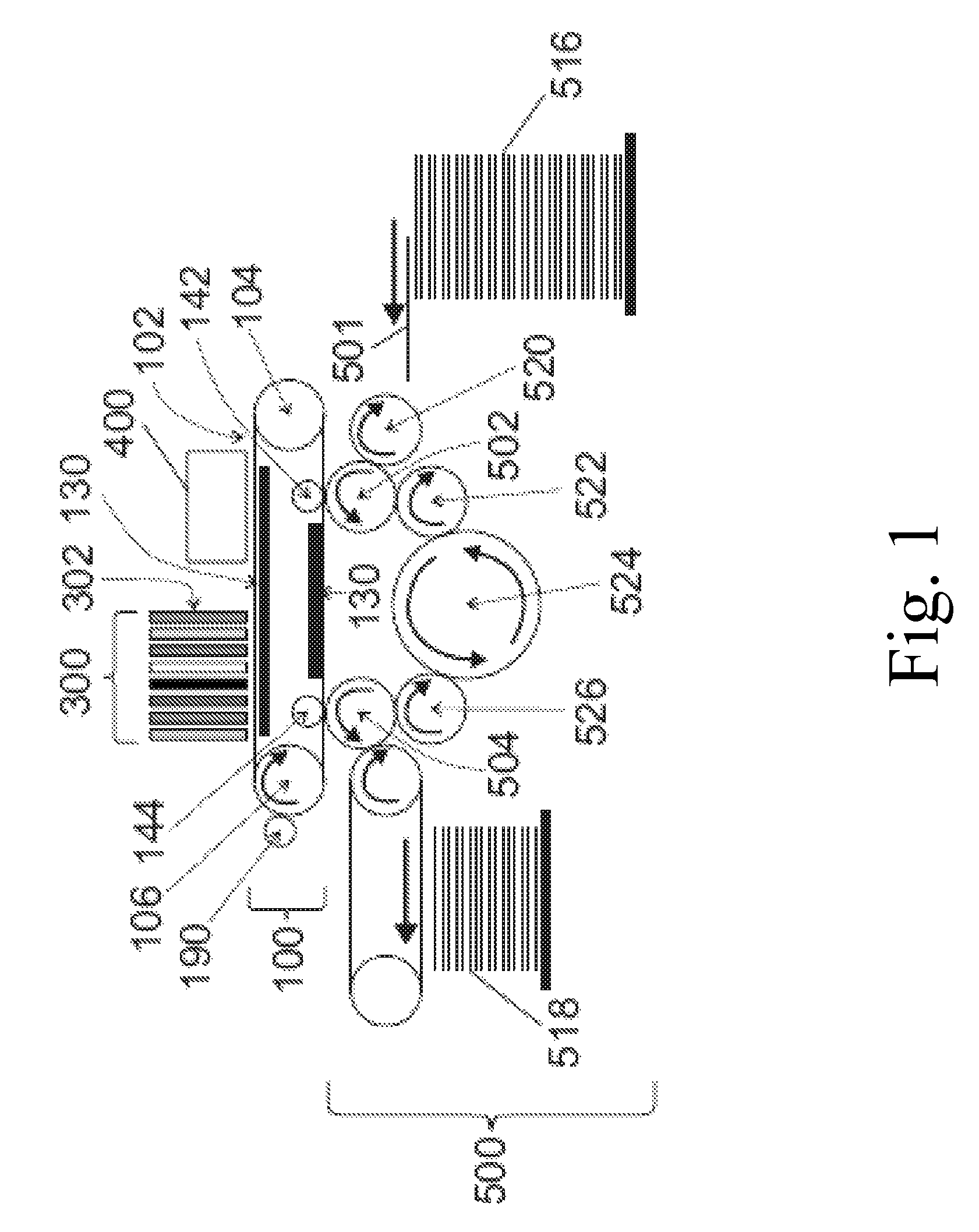
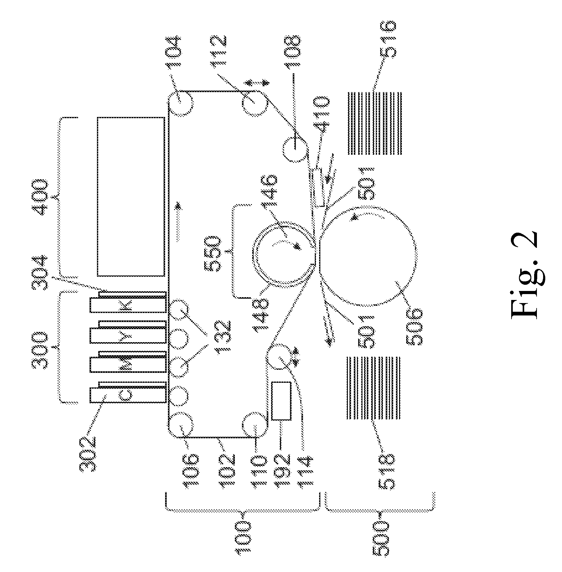
[0057]A hydrophobic outer surface on the intermediate transfer member is desirable as it assists in the eventual transfer of the residue film to the substrate. Such a hydrophobic outer surface or release layer is however undesirable during ink image formation, among other reasons because bead-like ink droplets cannot be stably transported by a fast moving intermediate transfer member and because they result in a thicker film with less coverage of the surface of the substrate. The presently claimed invention sets out to preserve, or freeze, the thin pancake shape of each ink droplet, that is caused by the flattening of the ink droplet on impacting the surface of the intermediate transfer member, despite the hydrophobicity of the surface of the intermediate transfer member, while also facilitating transfer of the ink droplet so frozen to a substrate.
[0100]As the outer surface of the intermediate transfer member is hydrophobic, there may be little (<1.5%) or substantially no swelling of the transfer member due to absorption of water from the ink; such swelling is known to distort the surface of transfer members in commercially available products utilizing silicone coated transfer members and hydrocarbon carrier liquids. Consequently, the process described above may achieve a highly smooth release surface, as compared to intermediate transfer member surfaces of the prior art.

Problems solved by technology

Such processes suffer from drawbacks.
In liquid ink processes, for instance, the use of organic-based solvents creates a challenging safety and environmental concern.
Direct ink jetting of liquid inks, typically aqueous, yields, on the other hand, limited resolution due to wicking of the inks into fibrous substrates, such as paper.
Though such problems might be partially addressed by the use of substrates with special coatings engineered to absorb the liquid ink in a controlled fashion or to prevent its penetration below the surface of the substrate, such a solution is not suitable for certain printing applications and its cost makes it not viable for commercial printing.
Furthermore, the use of coated substrates creates its own problems in that the surface of the substrate remains wet and additional costly and time consuming steps are needed to dry the ink, so that it is not later smeared as the substrate is being handled, for example stacked or wound into a roll.
In addition, excessive wetting of the substrate causes cockling and makes printing on both sides of the substrate (also termed perfecting or duplex printing) difficult, if not impossible.
Moreover, inkjet printing directly onto porous paper, or other fibrous material, results in poor image quality because of variation of the distance between the print head and the surface of the substrate.
This makes it more difficult to remove the water in the ink and also results in a small contact area between the droplet and the blanket that renders the ink image unstable during rapid movement.

Method used


Image

  • Treatment of release layer
  • Treatment of release layer
  • Treatment of release layer

Examples


example 1

[0155]An inkjet ink formulation was prepared containing:

[0156]

IngredientFunctionwt. %Carbon Black, Monarch ®Pigment1.5700 (Cabot)Joncryl ® 2038, 43.5%Resin13.8emulsion in water(6% solids)Tween ® 40Softening agent3.0Capstone FS-65 (DuPont)Non-ionic fluorosurfactant 0.01Water—Balanceto 100%Joncryl HPD 296 (35.5%Dispersant4.2water solution) (BASF)(solid resin)Ethylene glycol (Aldrich)Water-miscible co-solvent15  

[0157]Preparation procedure: A pigment concentrate, containing pigment (14%), water (79%) and Joncryl® HPD 296 (7%) were mixed and milled using a homemade milling machine. The progress of milling was controlled by particle size measurement (Malvern, Nanosizer). The milling stopped when the particle size (D50) reached 70 nm. Then the rest of the materials were added to the pigment concentrate. After mixing the ink was filtered through 0.5 micrometer filter.

[0158]The efficacy of various materials in improving the transfer of the black ink formulation described above were tested a...

example 2

[0164]Example 1 was repeated, but this time the surface of the CCRL PDMS release layer, instead of being spread with a thin film of ink, was printed with drops of ink of 9 picoliter drop size, using a Fujifilm Dimatix DMP-2800 printer (www.fujifilmusa.com / products / industrial_inkjet_printheads / deposition-products / dmp-2800 / index.html). Again, beading of the ink on the treated release layer surface was not observed, and results similar to those in Example 1 were obtained for both the PEI and amine functionalized silicone (SOL1 comprising about 1 wt. % of GP-4) treatments, for both coated and uncoated paper as above-identified.

example 3

[0165]Example 1 was repeated, but this time SOL4 (comprising about 2 wt. % GP-965) was used to treat the CCRL PDMS release layer instead of SOL1. A continuous shiny film was obtained on the coated paper for both the PEI and amine functionalized silicone treatments. Beading of the ink on the treated release layer surface was not observed. Printing on the uncoated paper showed that transfer from the PEI-coated portion of the release layer was not complete, but transfer from the GP-965-coated portion was complete.


PUM

PropertyMeasurementUnit
kinematic viscosityaaaaaaaaaa
thicknessaaaaaaaaaa
thicknessaaaaaaaaaa

Abstract

A method for treating a hydrophobic release layer of an intermediate transfer member for use in a printing process in which a negatively charged aqueous inkjet ink is jetted onto the surface of this layer. The method comprises contacting the release layer with a chemical agent which is an amine functionalized silicone. Transfer members comprising such a treated release layer and images printed therefrom are also disclosed.

Description

FIELD AND BACKGROUND[0001]The present invention relates to indirect printing systems and more particularly to compositions suitable for the treatment of intermediate transfer members.[0002]Digital printing techniques have been developed that allow a printer to receive instructions directly from a computer without the need to prepare printing plates, as in the more traditional offset methods. Various printing systems exist which may use either dry inks, such as the toners used in laser printers, or liquid inks having either organic or aqueous solvents or carriers. Such technologies may rely on direct application of inks in an image pattern onto paper or any other substrate, as in ink jetting commonly used in home and office printers, or they may rely on indirect printing in which a mirror image is first formed on an intermediate member and then transferred therefrom to the substrate. Such indirect method, more frequent in commercial settings, is exemplified by the liquid electro-phot...

Claims


Application Information

Patent Timeline
Patent Type & Authority Patents(United States)
IPC IPC(8): B41J2/005B41M5/03B41M5/025B41J2/01B41M5/36B41M5/00B41J2/21B41J11/00B41N10/00
CPCB41J2/0057B41J2/01B41M5/0256B41M5/03B41J2/2114B41J11/0015B41J2002/012B41M5/0011B41M5/36B41N10/00
Inventor LANDA, BENZIONSORIA, MEIRABRAMOVICH, SAGI
Owner LANDA
Why Eureka
Try Eureka