Cable mounting bracket apparatus and system

a bracket and cable technology, applied in the direction of electrical equipment, pipe supports, securing devices, etc., can solve the problems of high cost, maintenance and/or structural damage, unsatisfactory working conditions for workers, etc., and achieve the effect of stable bracket and low aspect ratio

Active Publication Date: 2017-02-21
STECHMANN ERIC
View PDF11 Cites 15 Cited by
  • Summary
  • Abstract
  • Description
  • Claims
  • Application Information

AI Technical Summary

Benefits of technology

[0010]In a third embodiment, the bracket has a low aspect ratio. This provides for a more stable bracket against exposure to the external forces common to elevated structures. In a fourth embodiment, the bracket has at least one hole in each of the at least two legs for the purpose of securing a cable using cable clamps, bolts, or other fastening devices.

Problems solved by technology

However, this type of installation has historically presented unsafe working conditions for the workers by obstructing and encumbering movement and rescue throughout access areas.
Additionally, these installations may cause maintenance and / or structural damage when installed on areas which lack initial design and structural capability.
Many of these installations, however, have historically been of high cost and are associated with additional safety, structural, and maintenance issues.
More specifically, traditional fastening of communication and electrical equipment onto areas such as ladders encumber the fluid motion of the workers' hands when grasping and transitioning along the side-rails.
Fastening devices such as clamps and bolted connections commonly encumber foot placement on rungs and further create abrasion risks for the worker or rescuer.
When workers and rescuers are subjected to these close-proximity coaxial cable installations they face exposure to radio-frequency waves which are known to cause bodily harm.
When scheduled for routine maintenance and renovation work, many of the aforementioned traditional fastening methods are difficult to temporarily move off of or away from the steel.
Many of these cables and antennae are temporarily re-erected onto a Cell-On-Wheels (C.O.W.) which is usually an expensive and logistically difficult scenario.
Due to the cost of the telecommunication equipment and ownership, many steel structure maintenance providers are prohibited from removing or repositioning such equipment.
It is common for this telecommunication equipment to remain fastened to the coated steel surface, presenting a surface preparation and coating obstruction.
This, in turn, causes the obstructed steel areas to not receive the proper corrosion repair and application of coatings.
Furthermore, many installations induce abrasion and corrosion to the steel structure through cyclic abrasive action between coatings and fastening connections and by increasing the moisture content below and adjacent to the fastening area.
Welding steel brackets onto the structure, especially an existing structure, is usually expensive, time intensive, requires specialized equipment and certification.
This creates a breach in the homogenous corrosion resistance application to the steel which may cause accelerated corrosion if left improperly repair coated.
Additionally, high temperatures induced from welding and grinding typically cause burning of the coatings near the site of the weld and obverse to the steel weld area.
Traditionally, the obverse side of many of these installations are left inadequately or completely devoid of proper repair.
While welded “stand-off” brackets come in a variety of shapes and sizes, they are not specifically designed to tangentially surface match with these curves and angles of the underlying steel structure.
Thus, these existing one-size-fits-all brackets do not maximize the surficial contact areas in order to provide the maximum amount application stability.
Previous designs also create sharp contact areas which regularly cause sharp abrasion pinch-points to underlying coatings.
Additionally, these installations are not low-profile when compared to the steel surface, creating obstructions within the cross-section of access areas.
This existing high-profile issue causes a top-heavy high profile connection which may structurally fail when induced to seasonal external environmental forces such as wind and ice dynamic loading characteristic of elevated structures.

Method used


Image

  • Cable mounting bracket apparatus and system
  • Cable mounting bracket apparatus and system
  • Cable mounting bracket apparatus and system

Examples


first embodiment

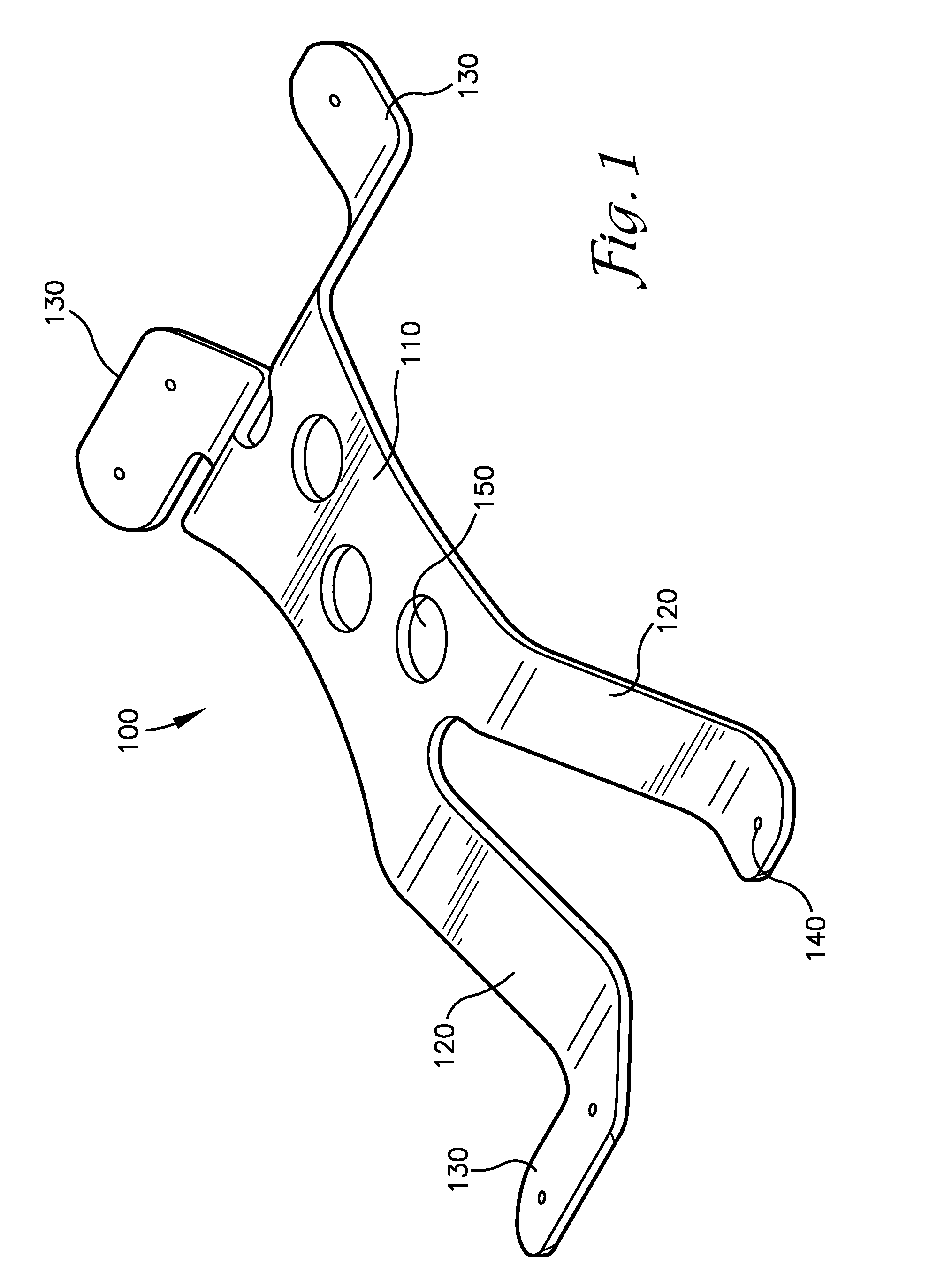
[0033]As shown in FIG. 1, the bracket 100 disclosed herein is comprised of a center connecting member 110 detachably connected to two sets of two legs 120. The distal end of each leg 130 contains at least one hole 140 through which a fastening device may be passed through and the bracket 100 may be adhered to a structure. The bracket 100 is preferably fabricated from a 10 gauge stainless steel alloy, such as austenitic 304 stainless steel. 304 stainless steel is composed of a minimum of 18% chromium and 8% nickel, combined with a maximum of 0.08% carbon. The legs 120 extend outwardly and downwardly to create a bracket with a wide stance and a low aspect ratio. The hole in the center connecting member 150 has a diameter preferably in the range of 0.10 to 1.25 inches in order to facilitate engagement with industry standard “snap-in” cable clamps, bolts, flexible fasteners such as zip ties, or other fastening devices to secure components.

[0034]Because the curvature of the distal ends o...

second embodiment

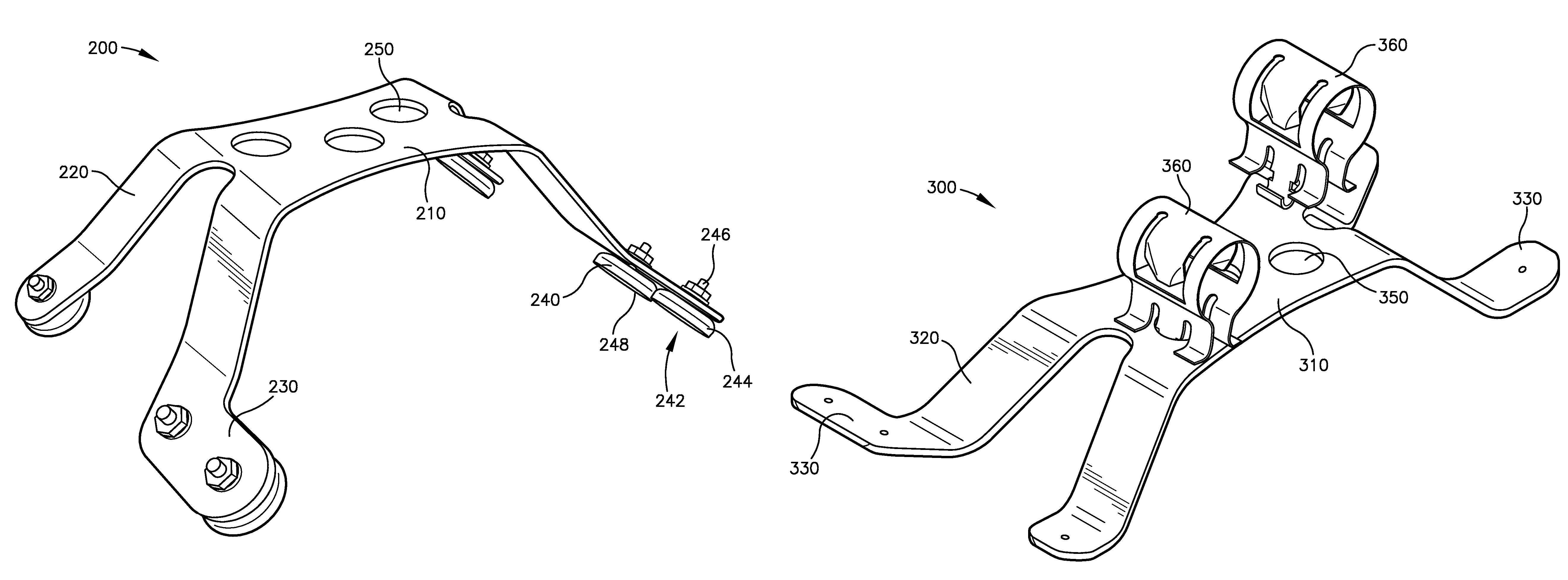
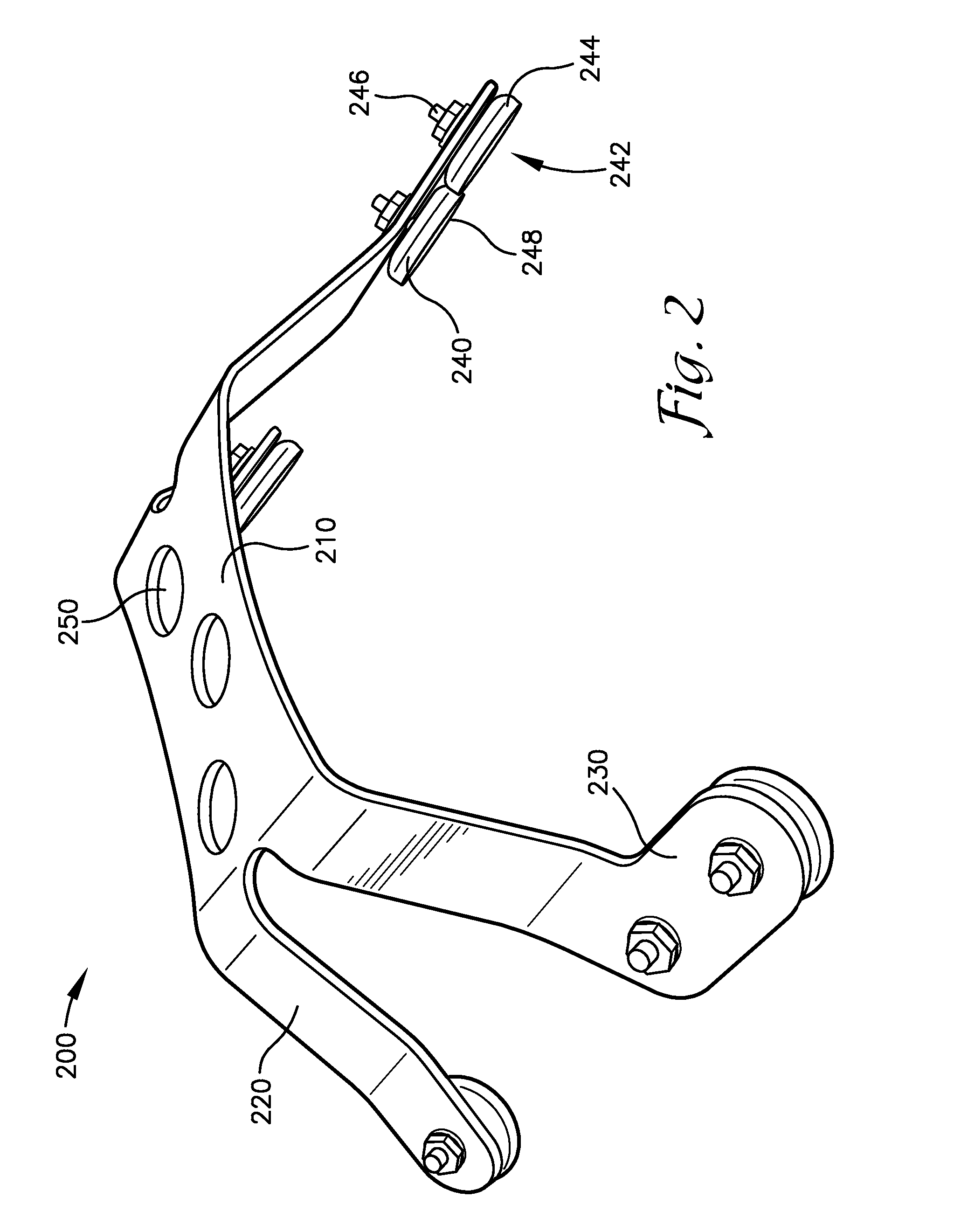
[0035]As shown in FIG. 2, the bracket 200 disclosed herein is comprised of a center connecting member 210, four legs 220, at least one hole in the center connecting member 250, and at least one magnetic pad 240 attached to the distal end of each leg 230.

[0036]One embodiment of the magnetic pad 240 is comprised of a rare-Earth alloy magnet 242 and corrosion resistant steel socket 244 with a corrosion resistant stem 246. Rare-Earth magnets generally have the greatest magnetic field strength per weight ratio of permanent magnets currently and commonly available. The magnetic pads 240 are attached to the distal end of each leg 230 of the bracket 200 either by threading the stem 246 or by pushing the stem 246 through the structure of the bracket and subsequently securing the magnet assembly with a combination of rivet or locking washer, locking nut and / or chemical locking compound so that the magnetic pads 240 are solidly fixed. The steel socket 244 encases the magnet 242 and tends to ma...


PUM


Abstract

A bracket and a cable mounting system which includes a bracket with a center panel or channel and with magnetic pads located on the distal ends of the center panel or channel so that the bracket may be attached to a structure by magnetic attraction. The cable mounting system may also consist of two brackets set a distance apart and a support rail placed in between and coupled to the brackets.

Description

RELATED APPLICATION[0001]This application is a continuation in part application to U.S. application Ser. No. 14 / 252,629 filed on Apr. 14, 2014, which claims priority to U.S. Provisional Application No. 61 / 811,424 filed Apr. 12, 2013, the disclosures of which are incorporated herein by reference.FIELD OF THE INVENTION[0002]This disclosure relates to brackets and mounting systems. More specifically, this disclosure concerns brackets and mounting systems used in elevated locations that are exposed to the outdoor and immersive areas.BACKGROUND OF THE INVENTION[0003]Historically, equipment from communication and electrical installations including; coaxial cables, conduit, wires, and other components which vertically traverse elevated structures have been fastened directly to worker access structures including; ladders, ladder cages, and hand rails. These structures have provided an immediate solution for equipment fastening. However, this type of installation has historically presented u...

Claims


Application Information

Patent Timeline
Patent Type & Authority Patents(United States)
IPC IPC(8): F16L3/00F16B1/00H02G3/32H02G3/30
CPCH02G3/32F16B1/00F16B2001/0035F16L3/00H02G3/305F16B2200/83
Inventor STECHMANN, ERIC
Owner STECHMANN ERIC
Why Eureka
Try Eureka