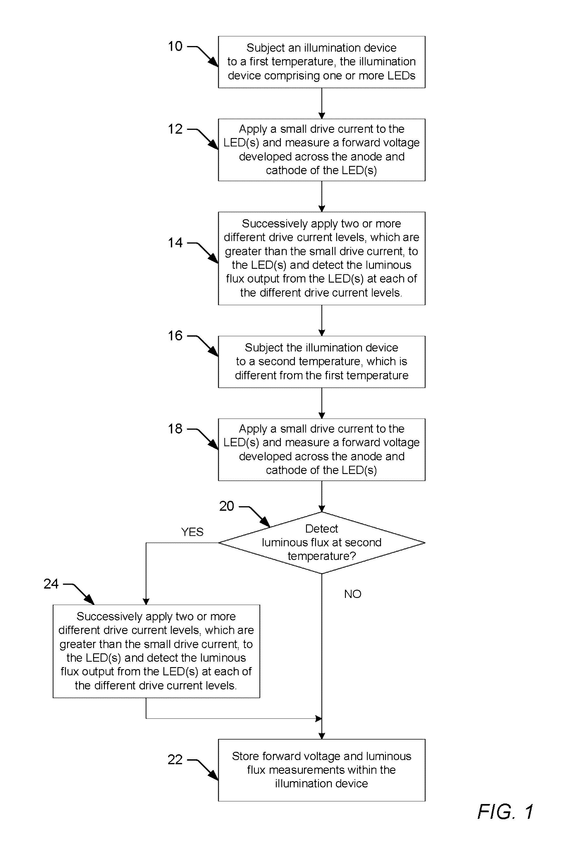
Although LEDs have many advantages over conventional light sources, a
disadvantage of LEDs is that their output characteristics tend to vary over temperature, process and time.
However, the
luminous flux generated by an LED for a given drive current does not remain constant over temperature and time, and gradually decreases with increasing temperature and as the LED ages over time.
However, binning alone cannot compensate for changes in LED output characteristics due to aging and temperature fluctuations during use of the LED device.
While heat sinks are generally needed for
thermal dissipation, adding temperature sensors to the
chip unnecessarily increases the cost of the LED device and consumes valuable
chip real estate.
More importantly, the temperature sensors and heat sinks added to the
chip often cannot provide an accurate
temperature measurement for all LEDs included with the LED device.
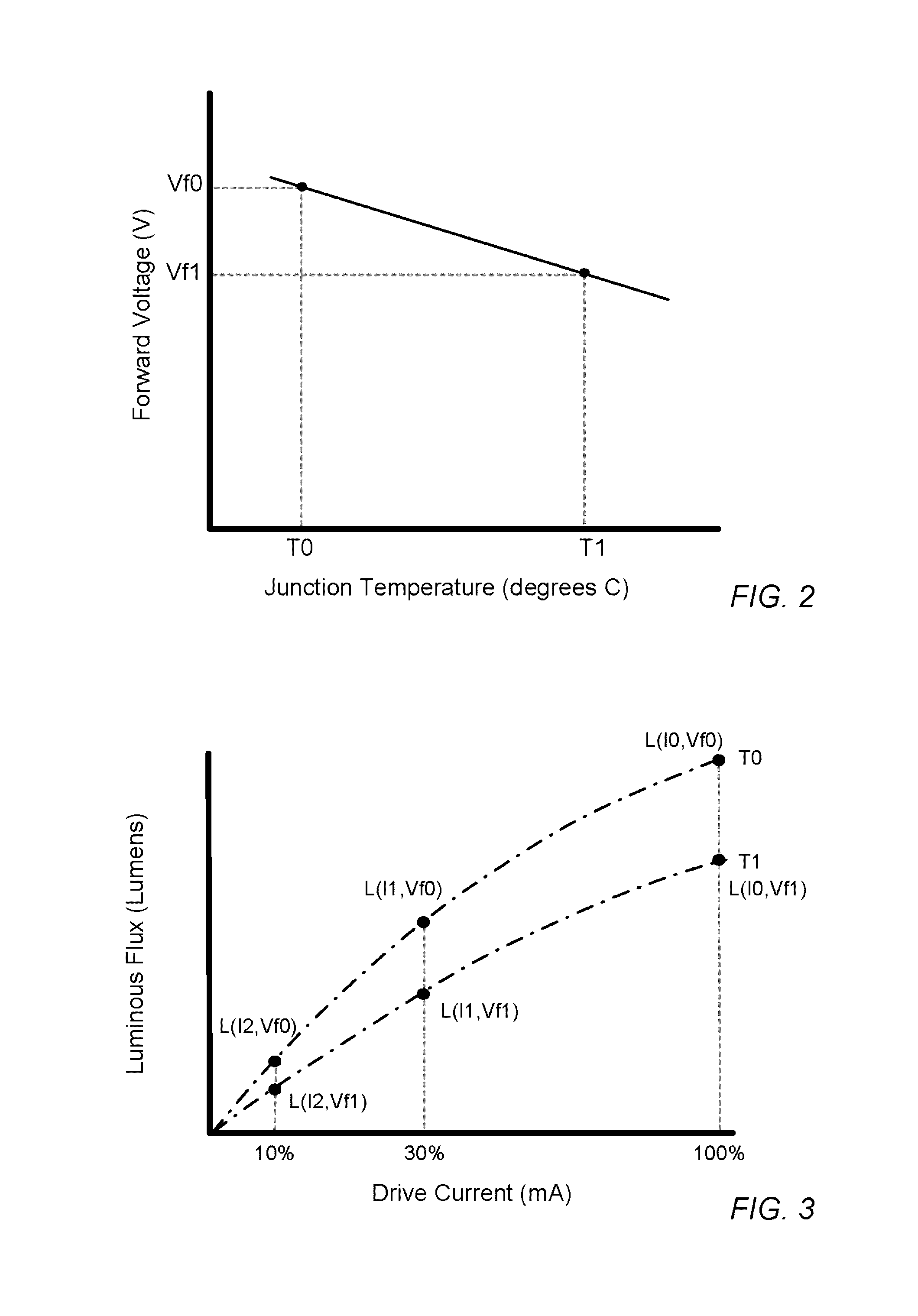
However, most manufacturers of conventional LED devices fail to account for the fact that the magnitude and slope of the line correlating
forward voltage to
junction temperature (shown, e.g., in FIG. 14) can vary significantly between LED manufacturers, LED part numbers and even individual LEDs arranged side by side on the same chip.
While the differences in slope are typically small, they can represent a few degrees C. measurement error over the
operating temperature range of an LED.
These measurement errors result in inaccurate temperature compensation if steps are not taken to account for these variations when calibrating conventional LED devices.
Without accounting for such non-linear behavior, conventional multi-color LED devices cannot be used to provide accurate temperature compensation for all LEDs included within the multi-color LED device.
However, FIG. 17 shows that the luminous flux produced by red, red-orange and, especially, yellow (amber) LEDs changes significantly and sometimes dramatically over temperature, and that these changes are substantially non-linear.
Conventional multi-color LED devices fail to provide calibration and compensation for each color of LED used in the device, and thus, fail to provide accurate temperature compensation in a multi-color LED device.
Without accounting for such non-linear behavior, conventional LED devices cannot be used to provide accurate temperature compensation for all LEDs included within the LED device.
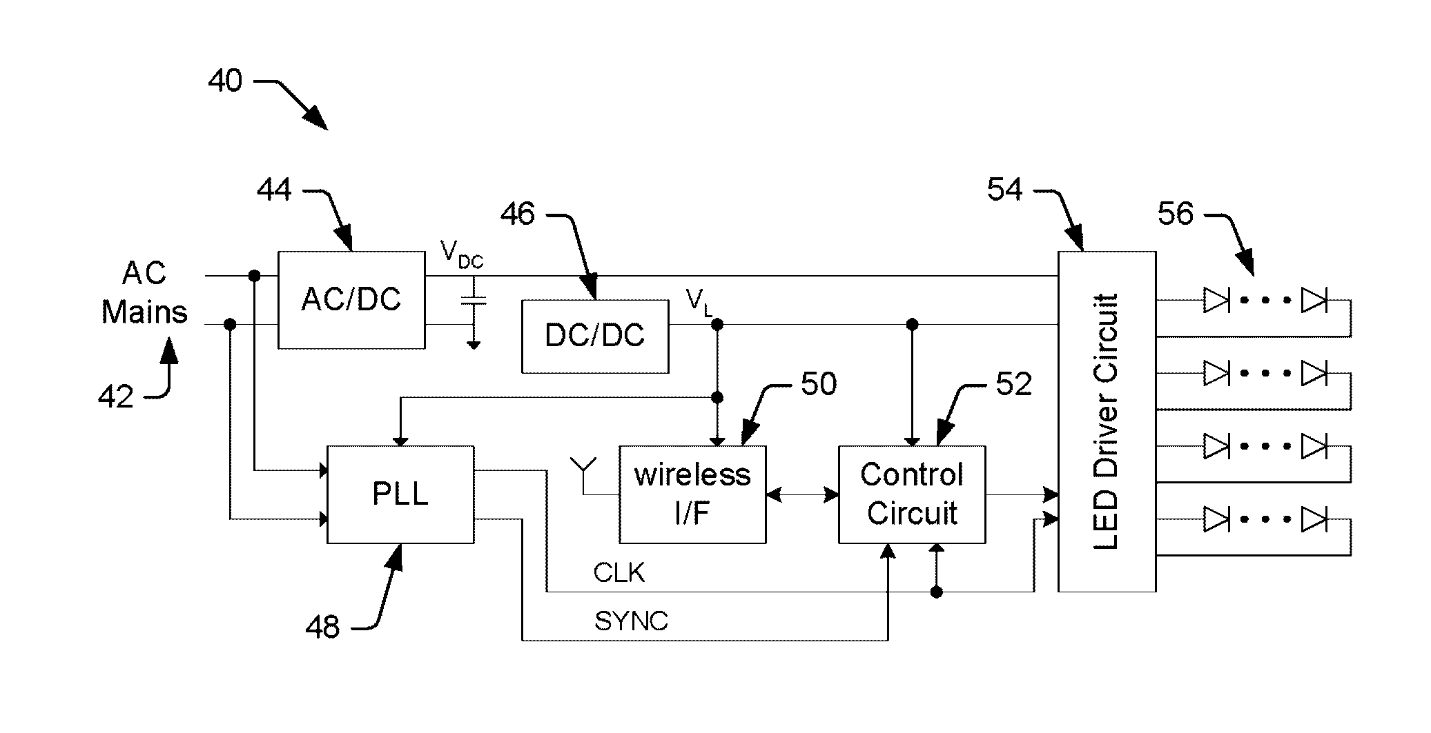
In addition to failing to account for non-linear behavior and differences in output characteristics between individual LEDs, conventional LED devices typically use
pulse width modulation (PWM) dimming to control the overall luminance of the LED device.
However, PWM dimming can be undesirable for a number of reasons.
On a more technical level, PWM dimming causes issues for the power supply and the LEDs when switching large amounts of currents on and off.
For example, in order to prevent the output
voltage from varying too much, a larger output
capacitor may need to be coupled across the power supply, which adds cost and consumes board space.
However, this does not address the transients that occur in the drive currents supplied to the LEDs whenever the drive currents are turned on and off.
Another issue arises, not only when using PWM dimming, but whenever groups of LEDs are periodically turned on and off for any reason in an
LED array.
Whenever LEDs are periodically turned on and off, even at an imperceptibly
high rate, an undesirable artifact called “brightness banding” occurs.

