Augmented propulsion system with boundary layer suction and wake blowing

a propulsion system and boundary layer technology, applied in the direction of aircraft navigation control, airflow influencers, jet flaps, etc., can solve the problems of large diameter engines that have diminished thrust capacity, pressure drag, and size of engine nacelles, so as to improve the performance and efficiency reduce exhaust temperature or acoustic emissions, and improve the effect of jet engine powered aircra

Active Publication Date: 2017-03-07
THE UNITED STATES OF AMERICA AS REPRESETNED BY THE SEC OF THE AIR FORCE
View PDF6 Cites 13 Cited by
  • Summary
  • Abstract
  • Description
  • Claims
  • Application Information

AI Technical Summary

Benefits of technology

[0010]According to one embodiment of the disclosed invention, a system to improve jet engine powered aircraft performance and efficiency is provided. The system includes a jet engine having a pressurized air port configured to convey a pressurized airflow from a compressor or a bypass fan disposed in the jet engine. A primary airfoil has a trailing edge, a top surface, and a boundary region. The system further includes a secondary airfoil disposed at a distance from the top surface of the primary airfoil. The secondary airfoil has a bottom surface and a trailing edge. An exhaust region is formed by the trailing edge of the primary airfoil and the trailing edge of the secondary airfoil. A primary airfoil ejector port and a secondary airfoil ejector port are pneumatically coupled to the pressurized air port. The primary airfoil ejector port is disposed proximate the boundary region and the secondary airfoil ejector port is disposed on the bottom surface.
[0011]According to another embodiment of the disclosed invention, a method of reducing fuel consumption, exhaust temperature, or acoustic emissions of a jet engine powered aircraft is provided. The method includes providing a primary airfoil and a secondary airfoil separated by an injection region. The method further includes introducing a pressurized airflow from the primary airfoil and from the secondary airfoil into the ejection region, wherein the pressurized airflow from the primary airfoil is introduced near a boundary region. An ambient airflow is combined with the pressurized airflow in the ejection region. The method further includes ejecting a mix of pressurized airflow and ambient air from an exhaust region aft of the ejection region.

Problems solved by technology

While this technique is effective at increasing fuel efficiency, it necessitates a larger diameter engine that has diminished thrust capacity when compared with a low BPR or pure turbojet configuration (particularly at higher airframe speeds).
Efficiency also suffers from resulting pressure drag at the location of flow separation near the top of an airfoil near the leading edge (i.e., the boundary region), the size of the engine nacelle, and wake turbulence.

Method used


Image

  • Augmented propulsion system with boundary layer suction and wake blowing
  • Augmented propulsion system with boundary layer suction and wake blowing
  • Augmented propulsion system with boundary layer suction and wake blowing

Examples


Embodiment Construction

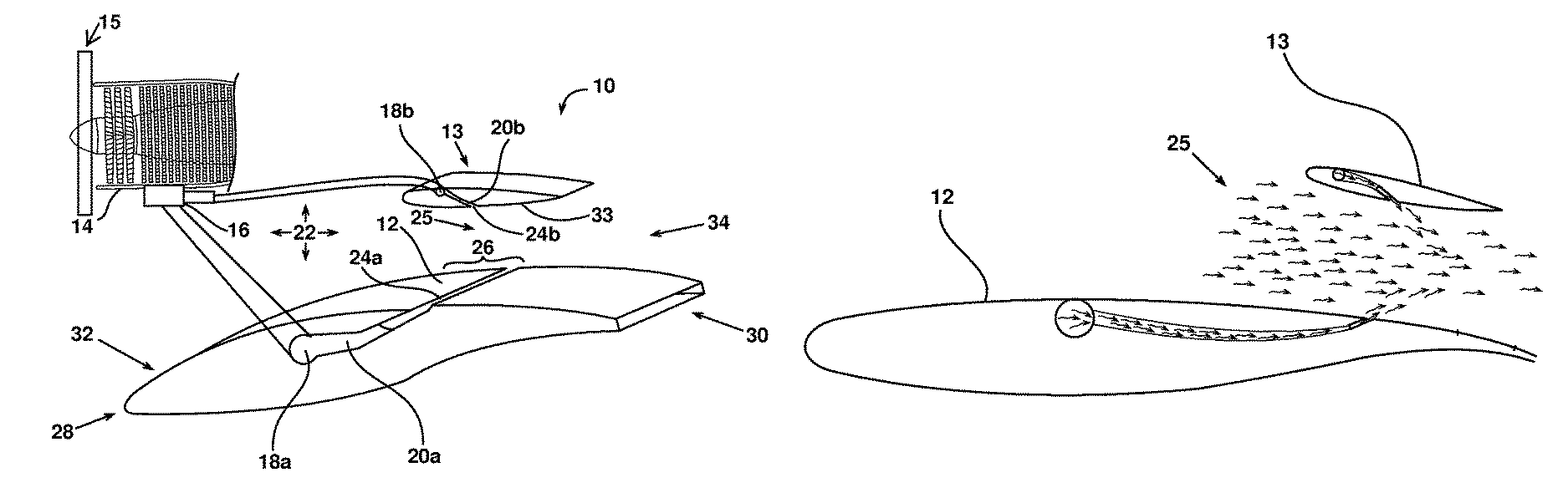
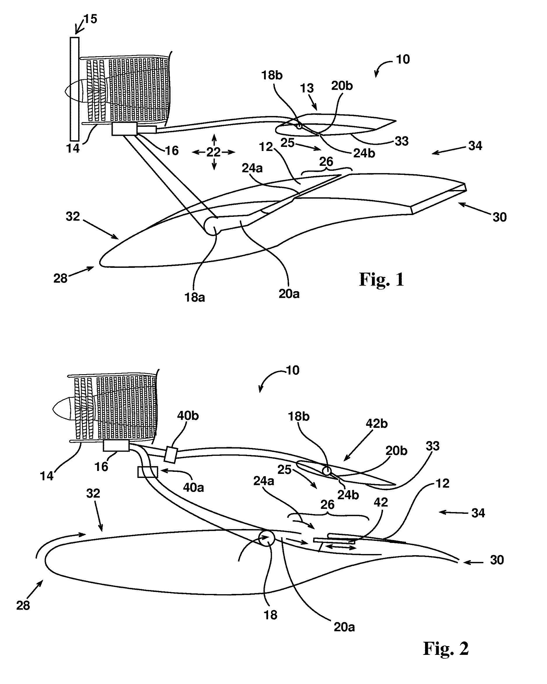
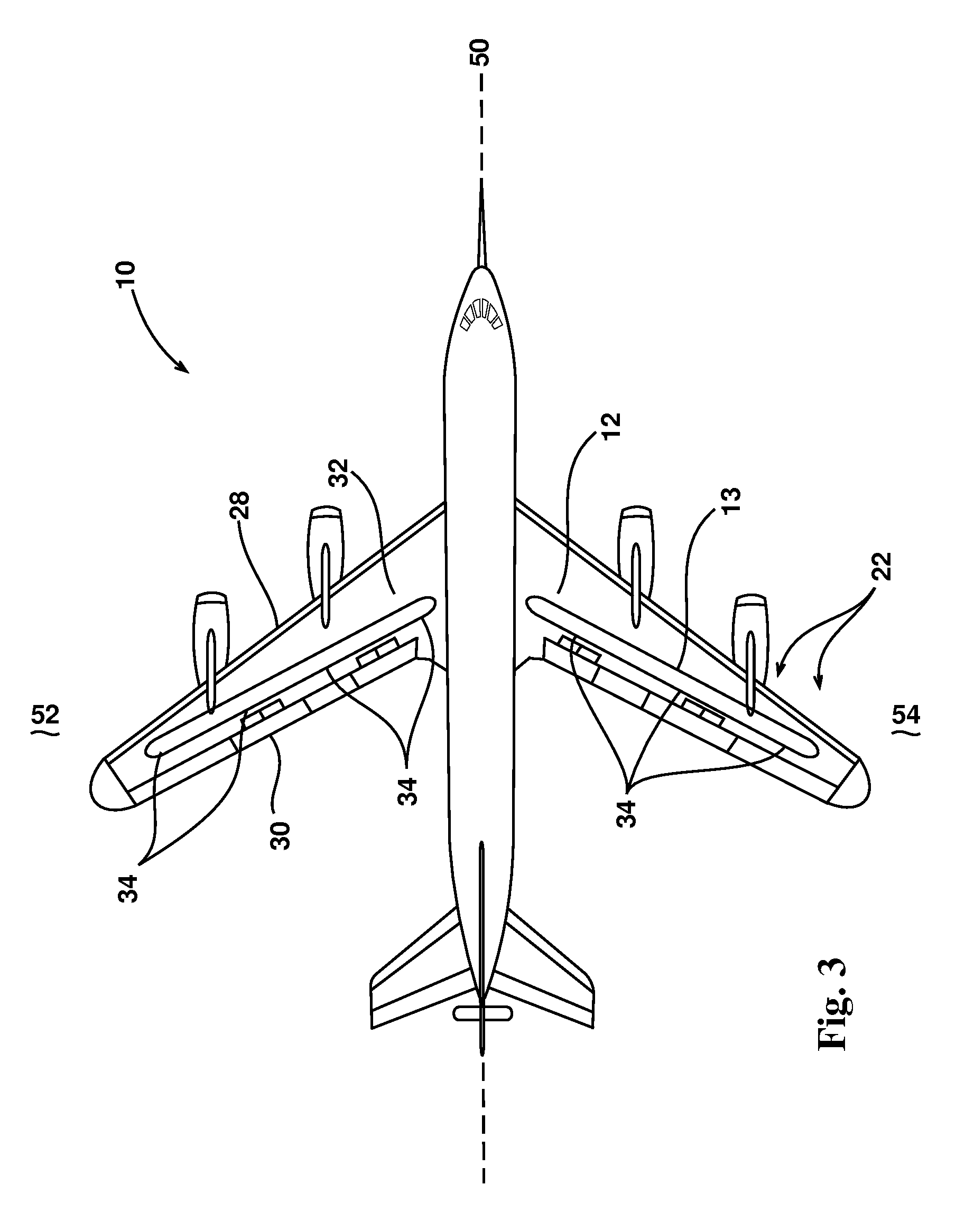
[0022]Turning attention to FIG. 1, a partial cross sectional perspective illustration shows an embodiment of the augmented propulsion system with boundary layer suction and wake blowing 10. The system 10 includes a primary airfoil 12, a secondary airfoil 13, and a compressor 14 as part of an aircraft (as shown in FIG. 3). The primary airfoil 12 and secondary airfoil 13 may be supported in a spaced arrangement by use of pylons or other structures known to one of ordinary skill in the art. In the alternative, engine nacelles or other structure surrounding a propulsion duct or exhaust may be disposed between the first airfoil 12 and the second airfoil 13 for support thereof.

[0023]The compressor 14 may comprise a single compressor stage disposed in a single jet engine assembly or a plurality of compressor stages disposed in a single assembly. The compressor 14 includes a pressurized air port 16 configured to convey air pressurized by the compressor 14. It should be noted that this press...


PUM


Abstract

A system to improve jet engine powered aircraft performance and efficiency includes a jet engine having a pressurized air port configured to convey a pressurized airflow from a compressor or a bypass fan disposed in the jet engine. A primary airfoil has a trailing edge, a top surface, and a boundary region. The system further includes a secondary airfoil disposed at a distance from the top surface of the primary airfoil. The secondary airfoil has a bottom surface and a trailing edge. An exhaust region is formed by the trailing edge of the primary airfoil and the trailing edge of the secondary airfoil. A primary airfoil ejector port and a secondary airfoil ejector port are pneumatically coupled to the pressurized air port. The primary airfoil ejector port is disposed proximate the boundary region and the secondary airfoil ejector port is disposed on the bottom surface.

Description

[0001]Pursuant to 37 C.F.R. §1.78(a)(4), this application claims the benefit of and priority to prior filed Provisional Application Ser. No. 61 / 817,703, filed 30 Apr. 2013, which is expressly incorporated herein by reference.RIGHTS OF THE GOVERNMENT[0002]The invention described herein may be manufactured and used by or for the Government of the United States for all governmental purposes without the payment of any royalty.FIELD OF THE INVENTION[0003]The present invention relates generally to apparatus and methods for improved fuel efficiency of jet powered aircraft and, more particularly, to the introduction of bleed air for propulsion augmentation and drag reduction.BACKGROUND OF THE INVENTION[0004]Operators of both military and civilian aircraft constantly endeavor to reduce the expenses associated with use of the aircraft. Since fuel consumption represents a significant portion of an aircraft's operating expenses, improved fuel efficiency is a persistent goal. To that end, it has...

Claims


Application Information

Patent Timeline
Patent Type & Authority Patents(United States)
IPC IPC(8): F02K3/02B64C15/14B64C9/38
CPCF02K3/025B64C9/38B64C15/14B64C3/28B64C21/04B64C21/08B64C39/08B64C2230/04B64C2230/06Y02T50/10
Inventor ROLLING, AUGUST JHEISER, WILLIAM HWISNIEWSKI, CHARLES F
Owner THE UNITED STATES OF AMERICA AS REPRESETNED BY THE SEC OF THE AIR FORCE
Why Eureka
Try Eureka