Valve replacement devices

a valve and valve technology, applied in the field of valve replacement devices, can solve the problems of existing embolic prevention devices, elderly patients with frailty, and other patients who may not have acute clinical deterioration but may suffer late effects, and most often elderly with frailty

Active Publication Date: 2017-03-14
EMSTOP INC
View PDF18 Cites 5 Cited by
  • Summary
  • Abstract
  • Description
  • Claims
  • Application Information

AI Technical Summary

Benefits of technology

[0006]An embolic material blocking catheter includes an integrated embolic material blocking element that is deployable within a blood vessel downstream of a treatment site to block embolic material released from the treatment site from flowing downstream through the blood vessel, thereby preventing associated embolism(s). For example, the integrated embolic material blocking element can be deployed in a patient's aorta downstream of the patient's aortic valve to block flow of embolic material released during implantation of a prosthetic aortic valve. In many embodiments, the embolic material blocking catheter includes a lumen into which a delivery catheter for the prosthetic valve can be inserted to advance the prosthetic valve to a implantation site upstream of the deployed embolic material blocking element. In many embodiments, the lumen is configured to accommodate extraction of embolic material blocked by the embolic material blocking element while also accommodating the delivery catheter. The embolic material blocking catheter and related delivery catheter, devices, and methods are especially suited for use in TAVR via any access (including, but not limited to, femoral, direct aortic access, brachiocephalic, subclavian, axillary or carotid arteries), which enables accurate positioning of the prosthetic aortic valve.
[0013]In many embodiments, the embolic material blocking catheter includes an insertion port for the delivery catheter. For example, the insertion port can be configured to accommodate insertion of a distal portion of the delivery catheter supporting the prosthetic valve in the pre-deployment configuration into the lumen of the elongated element and advancement of the distal portion of the delivery catheter through the lumen to position the prosthetic aortic valve upstream of the embolic material blocking element for deployment from the pre-deployment configuration. In many embodiments, the insertion port is configured to inhibit leakage from the lumen.

Problems solved by technology

Patients presently selected for TAVR, however, are most often elderly with frailty and a number of comorbidities.
Other patients may not have acute clinical deterioration but may suffer late effects due to impaired functional reserve related to sub-clinical embolic events.
The occurrence of embolic events during TAVR is a significant impediment to offering the technique to larger lower risk groups of patients.
There are a number of difficulties with these existing embolic prevention devices.
First, deployment of the devices requires additional time and can conflict with the performance of the valve procedure.
Second, deployment of the devices may lead to additional vessel trauma and liberation of embolic material.
Third, the deployment of the devices may be difficult and stability of deployment may make protection less than reliable.
Fourth, the devices do not protect the brain from all sources of blood flow and particularly posterior cerebral blood flow is not filtered.
Fifth, systemic embolization will still occur that may lead to intestinal, renal, and / or peripheral manifestations of ischemic gut, renal insufficiency and / or peripheral ischemia.
Sixth, coronary embolization and myocardial infarction may occur due to proximal embolization.

Method used


Image

  • Valve replacement devices
  • Valve replacement devices
  • Valve replacement devices

Examples


Embodiment Construction

[0054]In the following description, various embodiments of the present invention will be described. For purposes of explanation, specific configurations and details are set forth in order to provide a thorough understanding of the embodiments. However, it will also be apparent to one skilled in the art that the present invention may be practiced without the specific details. Furthermore, well-known features may be omitted or simplified in order not to obscure the embodiment being described.

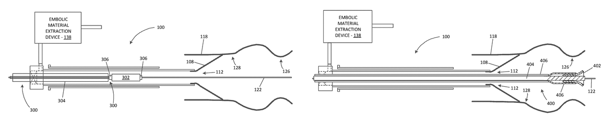
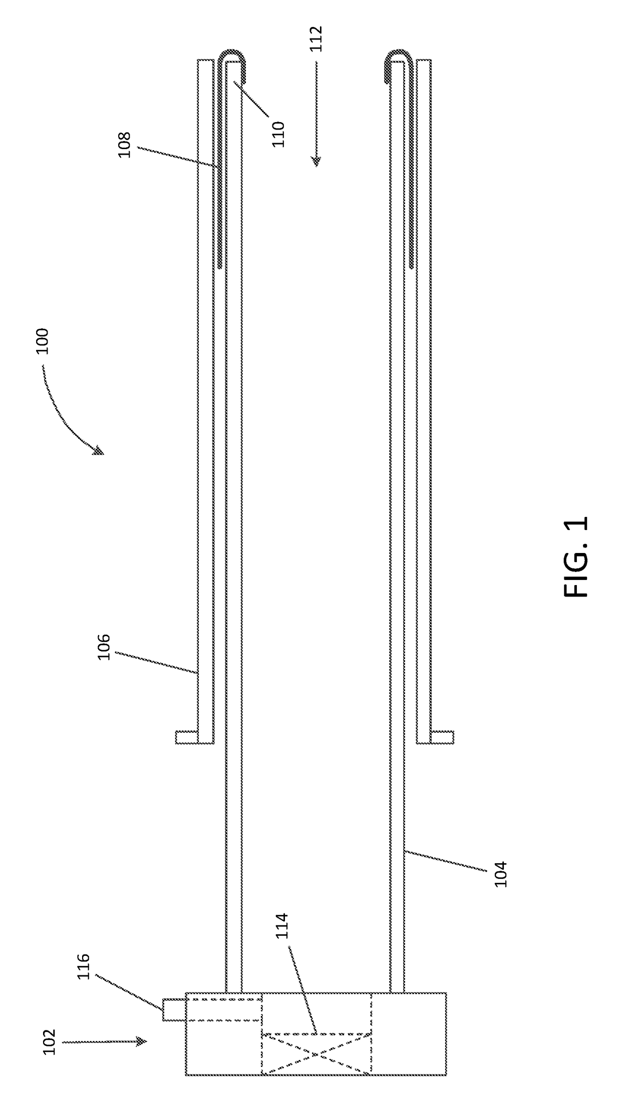
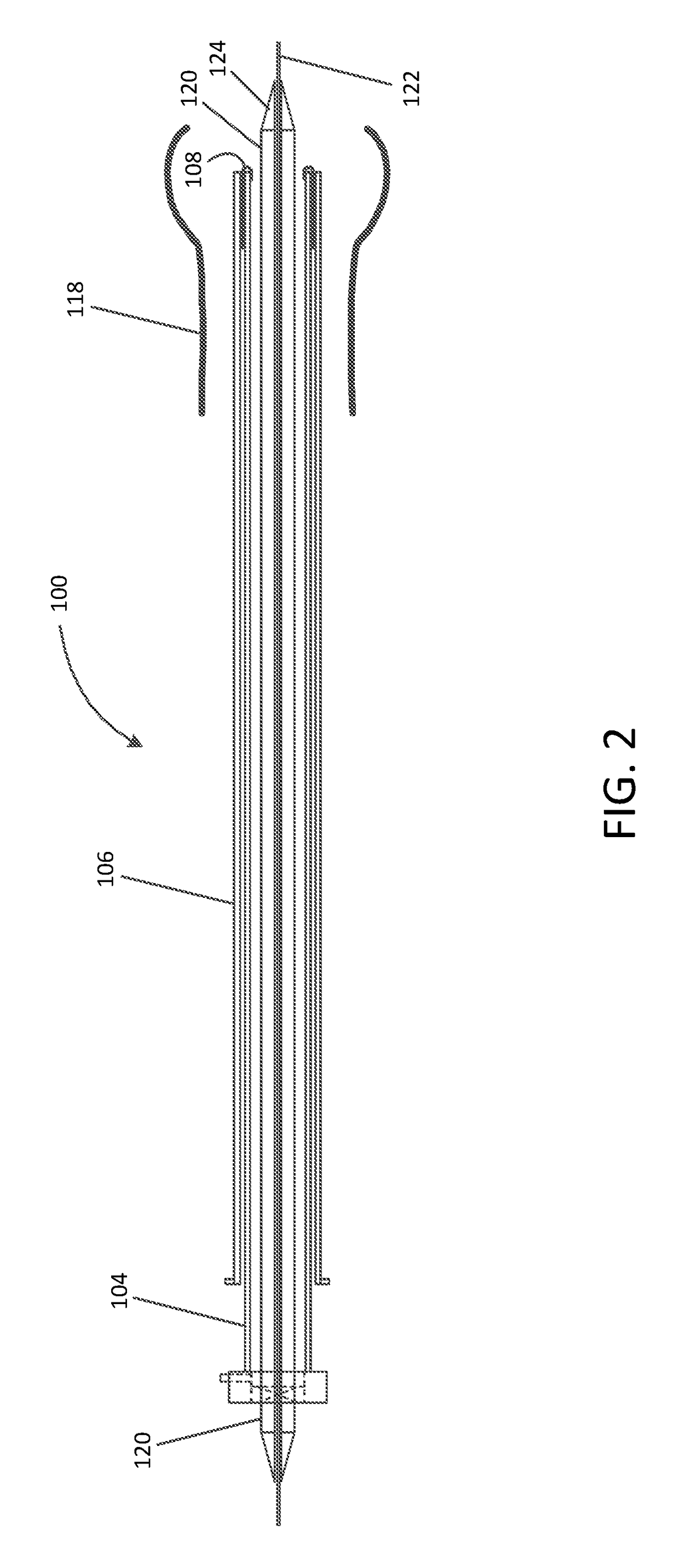
[0055]Referring now to the drawings, in which like reference numerals represent like parts throughout the several views, FIG. 1 is a simplified schematic drawing illustrating an embolic material blocking catheter 100 in an insertion configuration suitable for insertion into a blood vessel of a patient via any suitable insertion route, in accordance with many embodiments. The embolic material blocking catheter 100 includes a handle assembly 102, an elongated main tube 104, a retention sleeve 106, a...


PUM


Abstract

An embolic material blocking catheter includes a handle assembly, an elongated element having a lumen, and a deployable embolic material blocking element. The embolic material blocking catheter is configured to accommodate insertion of a treatment catheter into the lumen to position a treatment device distal to the embolic material blocking element for administering a treatment at a treatment site and / or convey embolic material blocked by the embolic material blocking element for extraction from the patient.

Description

CROSS-REFERENCES TO RELATED APPLICATIONS[0001]This application claims the benefit of U.S. Provisional Application No. 62 / 155,002, filed Apr. 30, 2015, which is incorporated herein by reference in its entirety for all purposes.BACKGROUND[0002]Transcatheter aortic valve replacement (TAVR) is a proven strategy for the treatment of severe aortic stenosis that has been validated for use in patients who are not eligible for surgical aortic valve replacement (SAVR) due to patient frailty or associated high operative risk. TAVR with the use of a self-expanding or balloon-expanded bioprosthetic valve has been FDA-approved for commercial use in the US in selected patients. TAVR is rapidly becoming the method of choice to treat aortic stenosis in patients deemed to be at increased risk of death if offered a traditional surgical aortic valve replacement. Patients presently selected for TAVR, however, are most often elderly with frailty and a number of comorbidities. The femoral artery is genera...

Claims


Application Information

Patent Timeline
Patent Type & Authority Patents(United States)
IPC IPC(8): A61F2/24A61F2/01
CPCA61F2/013A61F2/2427A61F2002/011A61F2002/016A61F2230/0006A61F2230/0067A61F2/011
Inventor GROH, MARK
Owner EMSTOP INC
Why Eureka
Try Eureka