Process and system for rapid sample analysis

a sample analysis and sample technology, applied in the field of process and system for rapid sample analysis, can solve the problems of short path length limit, and short path length limit the sensitivity of the technique, etc., and achieve the effect of low detection limit, low mdl, and low cos

Active Publication Date: 2017-03-28
MLS ACQ INC D B A MAX ANALYTICAL TECH
View PDF7 Cites 23 Cited by
  • Summary
  • Abstract
  • Description
  • Claims
  • Application Information

AI Technical Summary

Benefits of technology

[0011]In one aspect, a method for analyzing a sample comprises directing output from a temporally-resolved separator to a sample cell, e.g., a gas cell that integrates the components provided by the separator. Typically, the sample cell has been partially or fully evacuated. Fluids, e.g., gas(es) are allowed to accumulate in the sample cell, effectively integrating their spectral signatures. Multiple spectra obtained over a time interval can then be averaged to best measure the integrated concentration in the sample cell. Obtaining a moving background that includes spectra from a previously eluted sample component, e.g., previously eluted chemical species, allows for the analysis of the current eluting components without interference from previously eluted components. The integrated and averaged multiple spectra can be corrected by using a similarly collected moving background and the corrected data are compared to known spectra to identify one or more components, e.g., chemical species such as atoms, molecules, molecular fragments, ions, present in the current sample component.
[0043]Generally, the system described herein is rugged, requires limited service, with quick starts and restarts. It can be used in the field without concerns regarding instrument damage or long warm-up periods. Advantageously, the chromatography can run on N2. Pressures can be from near zero up to and potentially exceeding atmospheric. Some embodiments disclosed herein do not require helium, hydrogen, turbo pumps, electron ionization (EI) sources, or secondary GC detection devices, simplifying instrument operation and maintenance requirements. In many of its implementations, the invention allows any GC supplier or user to couple an existing GC to any commercial FTIR or other spectroscopic instrument.

Problems solved by technology

Nevertheless, the designs of existing GC-FTIR systems are also plagued with their own limitations.
Since IR absorption is proportional to cell path length, this short path length limits the sensitivity (minimum detection limit (MDL)) of the technique.
Problems also arise in cases in which GC peaks come off very quickly.
Since the light pipe has a relatively large volume when compared to the flow rates of the GC, the gas can become diluted, making measurements more difficult.

Method used


Image

  • Process and system for rapid sample analysis
  • Process and system for rapid sample analysis
  • Process and system for rapid sample analysis

Examples


example 1

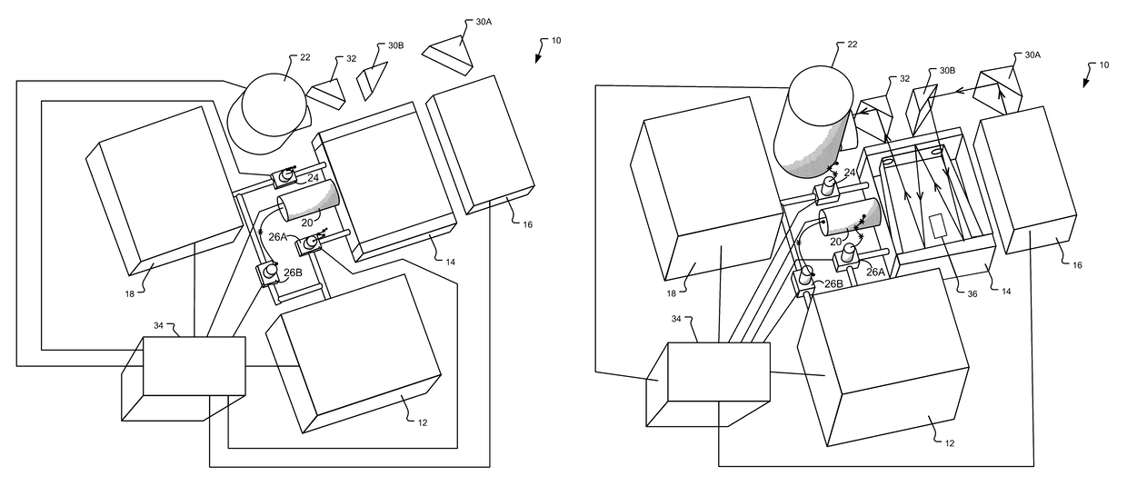
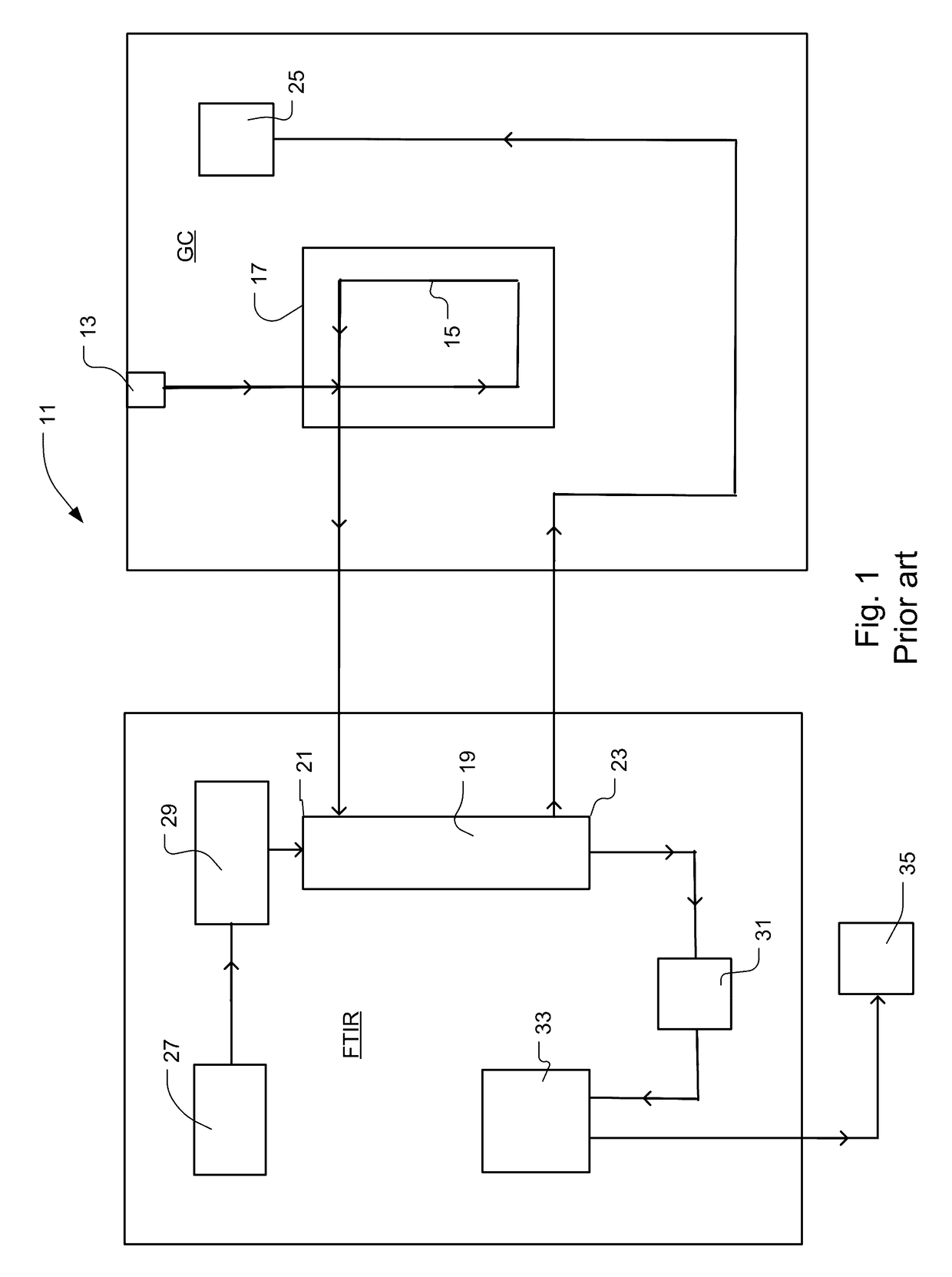
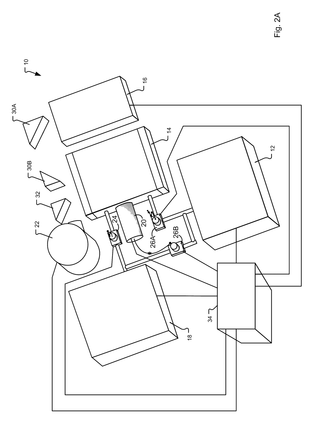
[0243]In a conventional GC-FTIR configuration, the gas leaves the GC and passes through the FTIR gas cell (usually a light pipe that is generally around 10 to 20 cm long) in a few seconds. If the concentration of a chemical compound is high enough, what is observed is a peak that rises and then falls, a behavior typical of any other detector. In contrast, using a system such as the system of FIGS. 2A and 2B, the gas can be collected in the gas cell for integration of each peak eluted from the GC.

[0244]A multiple path length gas cell can be utilized to generate a much higher absorbance since in the configuration described herein response time of the gas through the cell is not a concern. The absorbance increases linearly with the increased path length. Thus increasing the path length from a length of 10 cm (the actual length of the cell) to a multiple path of 5 m will produce a 50 times greater absorbance, assuming the same concentration in the in the sample cell described herein and...

example 2

[0258]These experiments were undertaken to demonstrate spectral aspects of the techniques described herein. A couple of screenshots of the fingerprint region of the IR spectrum from 550-1250 cm−1 were taken to demonstrate how the spectra change after post processing as described herein.

[0259]The graph in FIG. 9 is a final raw spectrum after a mixture of 60+ gases (compounds) is collected in the gas cell. Many of the gases were chlorinated and have strong absorption peaks at the low frequency end of the spectrum. All the features observed below 850 cm−1 are absorption peaks by some of the 60+ compounds. The peak PQR structure at 950-1150 cm−1 is indicative of the methanol which was the solvent.

[0260]Trying to analyze a spectrum for 60+ compounds with existing techniques, even when possible, proves to be exceedingly difficult, especially if identifying other unknowns is also desired.

[0261]If, however, protocols or algorithms described herein are applied across the data and inspecting ...


PUM

PropertyMeasurementUnit
volumesaaaaaaaaaa
volumeaaaaaaaaaa
flow ratesaaaaaaaaaa

Abstract

Components resolved in time by a separator accumulate in a sample cell and are analyzed by electromagnetic radiation-based spectroscopic techniques. The sample cell can be configured for multiple path absorption and can be heated. The separator can be a gas chromatograph or another suitable device, for example a distillation-based separator. The method and system described herein can include other mechanical elements, controls, procedures for handling background and sample data, protocols for species identification and / or quantification, automation, computer interfaces, algorithms, software or other features.

Description

RELATED APPLICATIONS[0001]This application claims the benefit under 35 USC 119(e) of U.S. Provisional Application No. 61 / 954,054, filed on Mar. 17, 2014, which is incorporated herein by reference in its entirety.BACKGROUND OF THE INVENTION[0002]Gas Chromatography (GC) is used to resolve a mixture into its various components according to retention profiles of the different molecules passing through the GC column. While the technique can separate mixtures containing hundreds of substances, identifying the molecules that elute from the column is more problematic. To address the need for rapid and sensitive identification of the molecular species present, GC has been integrated with techniques such as mass spectrometry (MS) or Fourier transform infrared (FTIR) spectrometry.[0003]Gas chromatography-mass spectrometry (GC-MS) is probably the most widespread tandem technique in the analytical instrumentation industry today. GC-MS systems are versatile and are employed across many different ...

Claims


Application Information

Patent Timeline
Patent Type & Authority Patents(United States)
IPC IPC(8): G01N21/31G01J3/42G01N30/74G01N30/86G01N21/35G01N21/3504G01N21/359G01N21/64G01N21/3581G01N21/65G01N21/03G01N30/00G01N30/02G01N21/33
CPCG01N30/74G01J3/42G01N21/3504G01N30/8606G01N30/8641G01N21/031G01N21/33G01N21/359G01N21/3581G01N21/64G01N21/65G01N2021/3595G01N2030/008G01N2030/025G01N2030/743
Inventor SPARTZ, MARTIN L.BONANNO, ANTHONY S.BEHNKE, PETER P.
Owner MLS ACQ INC D B A MAX ANALYTICAL TECH
Why Eureka
Try Eureka