LiDAR system comprising a single-photon detector

a detector and lidar technology, applied in the field of laser range finding, can solve the problems of limiting the laser power that can be used in the lidar system, affecting the measurement sensitivity in this wavelength regime, and the requirements of a lidar system used in automotive applications are quite challenging

Active Publication Date: 2017-04-18
LG INNOTEK CO LTD
View PDF5 Cites 52 Cited by
  • Summary
  • Abstract
  • Description
  • Claims
  • Application Information

AI Technical Summary

Benefits of technology

[0010]To further reduce the impact of solar-background-induced noise, in some embodiments, the single-photon detector is operated in a “range-gated” mode. In such operation, each detection frame includes a plurality of sub-gate periods, each including a different portion of the detection frame. The single-photon detector is armed at the beginning of each sub-gate period and disarmed at the end of each sub-gate period. As a result, each of the sub-gate periods corresponds to a longitudinal slice of the detection field. By cycling through a series of detection frames, each including the plurality of sub-gate periods, the present invention enables high signal-to-noise operation with high resolution over the entire field-of-view. By using short sub-gate periods, the probability of detecting a noise photon associated with the solar background in any individual sub-gate period is dramatically reduced.
[0011]In some embodiments, the results from multiple detection frames are processed using statistical analysis techniques to reduce the impact of the receipt of noise photons. In some embodiments, the results from multiple detection frames are collected in a dataset and digital thresholding is applied to the dataset to mitigate the effects of background noise.

Problems solved by technology

The requirements for a LiDAR system used in automotive applications are quite challenging.
The need for high-resolution performance would normally dictate the use of high laser power to ensure sufficient return signal from objects as far away as 300 m. Unfortunately, eye safety considerations limit the laser power that can be used in a LiDAR system.
Unfortunately, the solar background is quite high at 1550 nm and can degrade measurement sensitivity in this wavelength regime.
As a result, many prior-art LiDAR systems operate in the wavelength range from approximately 800 nm to approximately 1050 nm at low optical power levels, thereby sacrificing system performance.
Some prior-art LiDAR systems do operate 1550 nm; however, FOV is normally restricted to mitigate the effects of the solar background radiation.
Unfortunately, such an operational mode reduces the update rate for the system.
To develop a sufficiently large image of the surrounding region, therefore, multiple systems having overlapping fields of view are required, which increases overall cost and system complexity.

Method used


Image

  • LiDAR system comprising a single-photon detector
  • LiDAR system comprising a single-photon detector
  • LiDAR system comprising a single-photon detector

Examples


Embodiment Construction

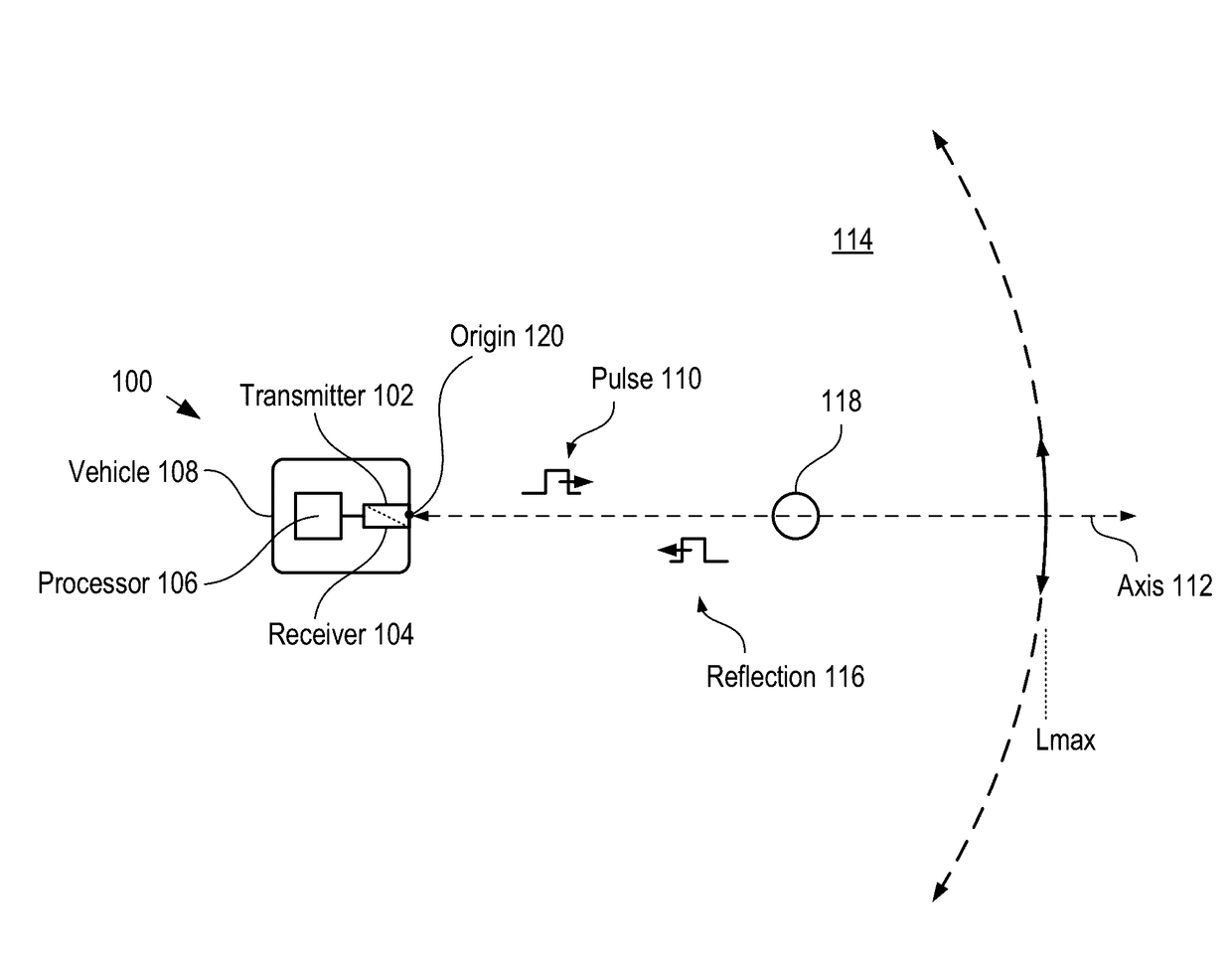
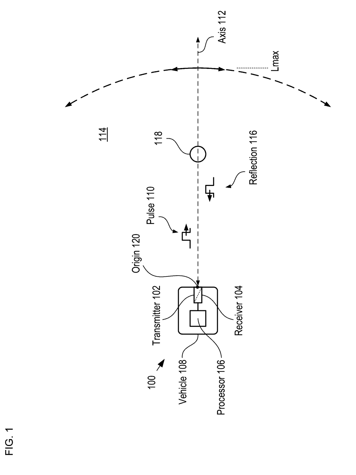
[0023]FIG. 1 depicts a schematic drawing of a LiDAR system in accordance with the illustrative embodiment of the present invention. System 100 includes transmitter 102, receiver 104, and processor 106.

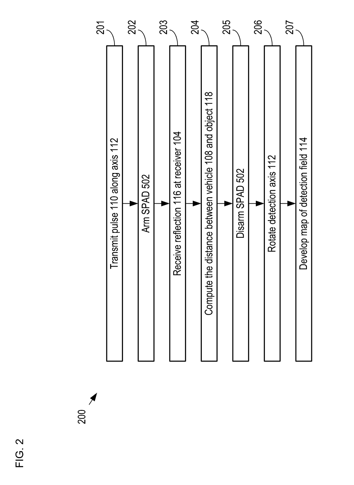
[0024]FIG. 2 depicts operations of a method for developing a map of objects in a detection field in accordance with the illustrative embodiment of the present invention. Method 200 begins with operation 201, wherein transmitter 102 transmits a train of pulses 110 along detection axis 112.

[0025]Transmitter 102 is an optical transmitter suitable for emitting a train of optical pulses having a wavelength within the range of approximately 1350 nm to approximately 1390 nm. Typically transmitter 102 generates the optical pulses using a laser source, such as a diode laser.

[0026]One skilled in the art will recognize that the performance of a LiDAR system is based on several factors, such as available optical power, the sensitivity of the detector used to detect reflected pulses, and the desire...


PUM


Abstract

A method for developing a map of objects in a region surrounding a location is disclosed. The method includes interrogating the region along a detection axis with a series of optical pulses and detecting reflections of the optical pulses that originate at objects located along the detection axis. A multi-dimensional map of the region is developed by scanning the detection axis about the location in at least one dimension. The reflections are detected via a single-photon detector that is armed using a sub-gating scheme such that the single-photon detector selectively detects photons of reflections that originate only within each of a plurality of zones that collectively define the detection field. In some embodiments, the optical pulses have a wavelength within the range of 1350 nm to 1390 nm, which is a spectral range having a relatively high eye-safety threshold and a relatively low solar background.

Description

FIELD OF THE INVENTION[0001]The present invention relates to laser range finding in general, and, more particularly, to LiDAR.BACKGROUND OF THE INVENTION[0002]Light Detection And Ranging (LiDAR) systems are attractive for use in many applications, such as driverless automobiles, farm equipment, and the like. Laser range finding is used to determine the range from a source to an object by sending a pulse of light in the direction of the object, detecting a reflection of the pulse, and determining the time required for the light to travel to and return from the object (i.e., its time-of-flight).[0003]A typical prior-art LiDAR system creates a local map around a vehicle by performing laser range finding in several directions and elevations around the vehicle. Prior-art systems accomplish this in different ways, such as using an array of laser sources, rotating a single laser source about an axis through the vehicle, or directing the output signal from a single source about the vehicle ...

Claims


Application Information

Patent Timeline
Patent Type & Authority Patents(United States)
IPC IPC(8): G01C3/08G01S17/42G01S7/487G01S17/10G01S17/89G01S17/18
CPCG01S17/89G01S7/487G01S17/107G01S17/42G01S17/18
Inventor KOTELNIKOV, EVGENII YURYEVICHMORDARSKI, WILLIAM PAULKUDRYASHOV, IGORENTWISTLE, MARK D.RANGWALA, SABBIR SAJJAD
Owner LG INNOTEK CO LTD
Why Eureka
Try Eureka