Vehicle including power storage unit

a technology of power storage unit and power storage unit, which is applied in the direction of engine-driven generator propulsion, electric device, final product manufacturing, etc., can solve the problems of power storage unit non-functionality, deterioration of battery, gradual decrease of capacity, etc., to prevent deterioration of power storage unit, promote the solidification of reaction product, and promote the effect of reaction product solidification

Active Publication Date: 2017-05-09
SEMICON ENERGY LAB CO LTD
View PDF32 Cites 2 Cited by
  • Summary
  • Abstract
  • Description
  • Claims
  • Application Information

AI Technical Summary

Benefits of technology

[0010]In view of the above, an object of one embodiment of the present invention is to prevent deterioration of a power storage unit or the like or repair the power storage unit or the like that has deteriorated, and to maximize the charge and discharge performance of the power storage unit or the like to maintain the charge and discharge performance of the power storage unit or the like for a long time.
[0076]According to one embodiment of the present invention, a reaction product (dross) deposited on an electrode surface can be removed by applying a signal (inversion pulse current) that makes a current flow between a positive electrode and a negative electrode in the direction opposite to that of the current with which the reaction product is formed. Hence, according to the one embodiment of the present invention, the electrode surface that has changed can be restored to the initial state or the electrode surface can be prevented from changing, resulting in a power storage unit that does not deteriorate in principle. In other words, a maintenance-free power storage unit is achieved, which allows a device or a vehicle including the power storage unit to be used for a long time.

Problems solved by technology

A power storage unit such as a lithium-ion battery deteriorates because of repeated charge and discharge and the capacity thereof is gradually decreased.
The voltage of the power storage unit is eventually out of the range where an electronic device including the power storage unit can be used, which makes the power storage unit non-functional.
Power storage units are electrochemical devices whose lifetimes are difficult to estimate individually in advance.

Method used


Image

  • Vehicle including power storage unit
  • Vehicle including power storage unit
  • Vehicle including power storage unit

Examples


embodiment 1

(Embodiment 1)

[0115]FIG. 3 illustrates an example of a structure of a vehicle 100 of one embodiment of the present invention. The vehicle 100 includes a power storage unit 120, a DCDC converter 104, an inverter 105, an electric motor 106, an engine 107, a power switching unit 140, and a control unit 130.

[0116]The electric motor 106 and the engine 107 are connected to wheels 110 through the power switching unit 140. The electric motor 106 and the engine 107 serve as power sources for driving the wheels 110. The power switching unit 140 has a function of selecting whether the wheels 110 are driven by the power of either or both of the electric motor 106 and the engine 107. The power switching unit 140 may include a transmission.

[0117]The electric motor 106 may be a direct-current (DC) motor or an alternate-current (AC) motor. In this embodiment, a three-phase AC motor is used as the electric motor 106. The engine 107 may be an internal combustion engine such as a gasoline engine, a di...

embodiment 2

(Embodiment 2)

[0143]FIG. 4 illustrates an example of a structure of a vehicle 150 of one embodiment of the present invention. The vehicle 150 has a structure in which another power storage unit and a charge and discharge control device 300 are added to the vehicle 100 shown in Embodiment 1.

[0144]The vehicle 150 shown in this embodiment includes a first power storage unit 121a and a second power storage unit 121b. When the plurality of power storage units are provided and the charge and discharge of the power storage units are controlled by the charge and discharge control device 300, inversion pulse operation can be performed in the discharging period as well as in the charging period.

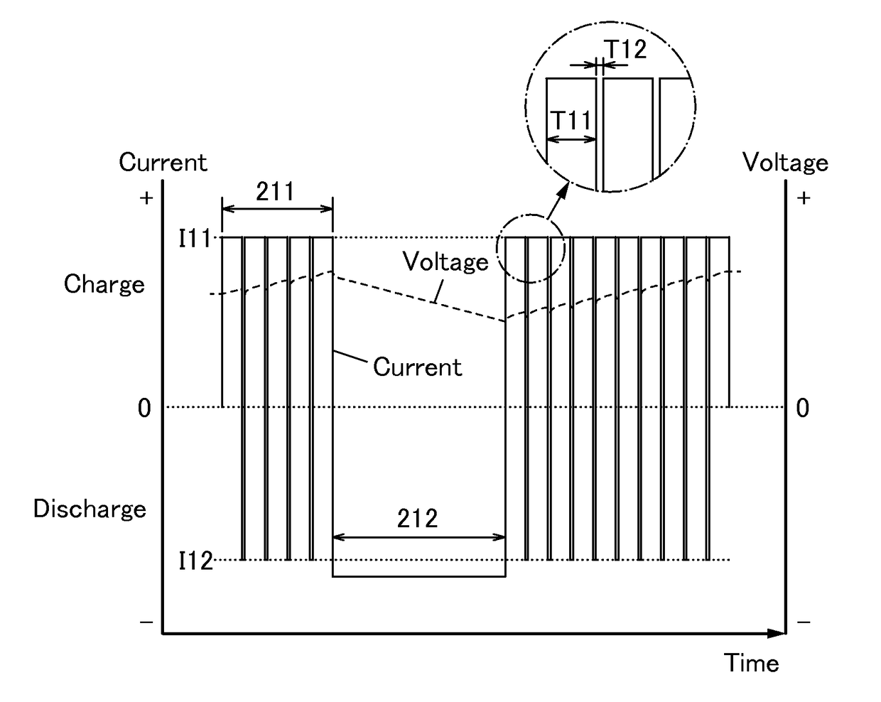
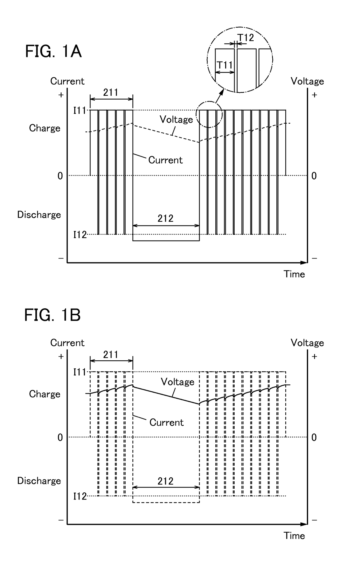
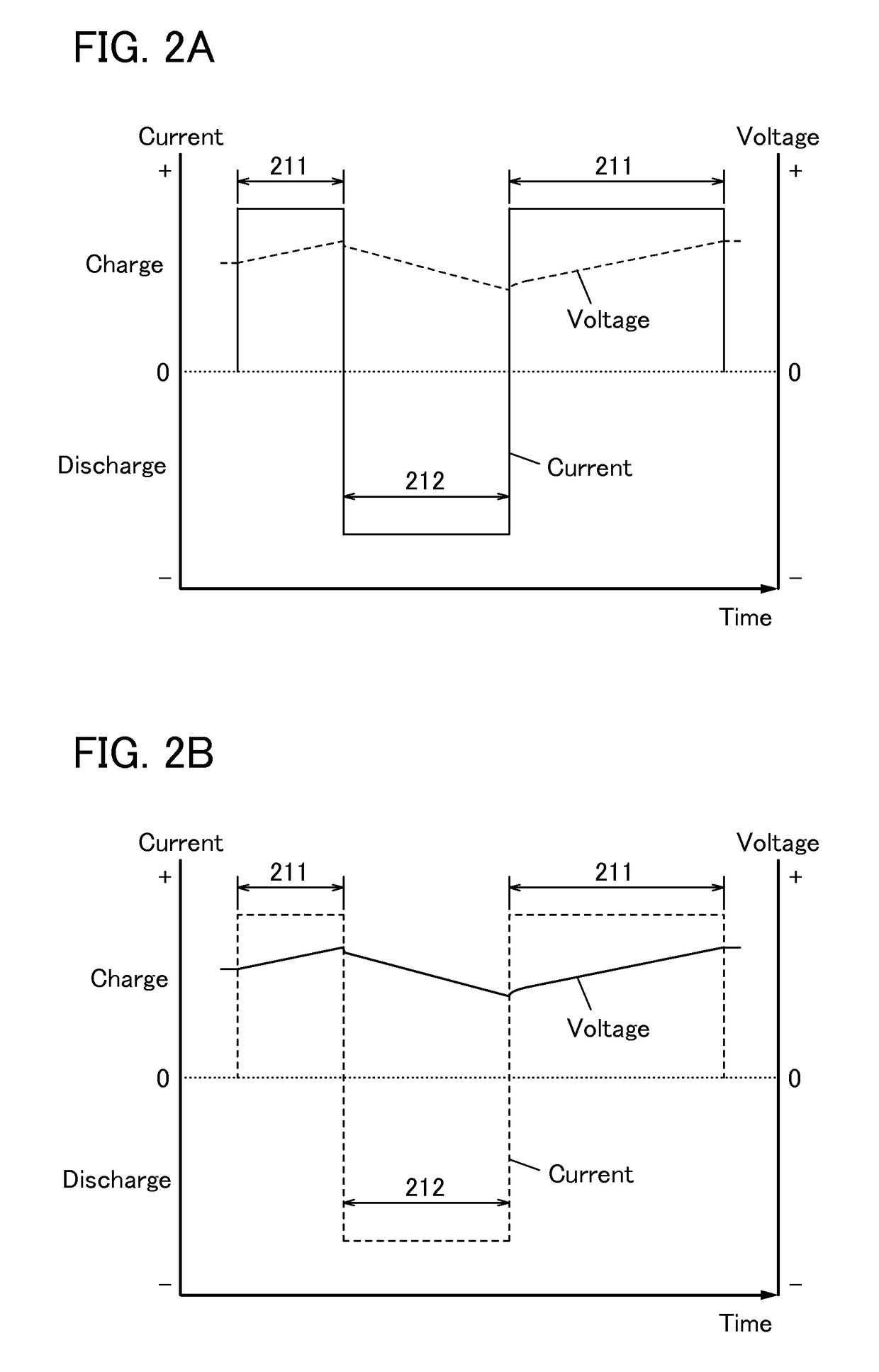
[0145]FIGS. 5A and 5B show an example of the inversion pulse operation. The inversion pulse operation is performed during a period (discharging period) in which the electric motor 106 is driven by one of the first and second power storage units 121a and 121b. Note that for easy viewing, FIGS. 5A and 5B...

embodiment 3

(Embodiment 3)

[0181]As an example of the power storage unit, a nonaqueous secondary battery typified by a lithium-ion secondary battery will be described.

[1. Positive Electrode]

[0182]First, a positive electrode of the secondary battery will be described with reference to FIGS. 16A and 16B.

[0183]A positive electrode 6000 includes, for example, a positive electrode current collector 6001 and a positive electrode active material layer 6002 formed on the positive electrode current collector 6001 by a coating method, a CVD method, a sputtering method, or the like. FIG. 16A shows an example in which the positive electrode active material layer 6002 is provided on both surfaces of the positive electrode current collector 6001 with a sheet shape (or a strip-like shape); however, one embodiment of the present invention is not limited to this example. The positive electrode active material layer 6002 may be provided on one of the surfaces of the positive electrode current collector 6001. Furt...


PUM

PropertyMeasurementUnit
negative electrode potentialaaaaaaaaaa
timeaaaaaaaaaa
currentaaaaaaaaaa

Abstract

Deterioration of a power storage unit included in a vehicle is prevented or the power storage unit that has deteriorated is repaired, and the charge and discharge performance of the power storage unit is maximized to be maintained for a long time. Attention has focused on a reaction product formed on an electrode surface which causes malfunction or deterioration of a power storage unit such as a lithium-ion secondary battery. In the power storage unit used for a vehicle that runs on the power of an electric motor, rapid discharge occurring in the acceleration of the vehicle or the like tends to promote the solidification of the reaction product. The reaction product is removed by application of an electrical stimulus, specifically, an inversion pulse voltage.

Description

BACKGROUND OF THE INVENTION[0001]1. Field of the Invention[0002]The present invention relates to an object, a method, or a manufacturing method. The present invention also relates to a process, a machine, a manufacture, or a composition of matter. In particular, the present invention relates to, for example, a semiconductor device, a display device, a light-emitting device, a power storage device, a driving method thereof, or a manufacturing method thereof. In particular, the present invention relates to, for example, a power storage unit or a vehicle including the power storage unit. In particular, the present invention relates to, for example, a method for charging a power storage unit or a vehicle including the power storage unit. In particular, the present invention relates to, for example, a method for discharging a power storage unit or a vehicle including the power storage unit. The present invention relates to a power storage system. In particular, the present invention rela...

Claims


Application Information

Patent Timeline
Patent Type & Authority Patents(United States)
IPC IPC(8): H02P1/00H01M10/0525B60L3/00B60L3/12H01M10/44B60L11/18H01M4/13H02J7/34H02J7/14H02J7/00H02J1/10B60L50/16
CPCB60L11/1809B60L3/0046B60L3/12B60L11/1859B60L11/1862H01M4/13H01M10/0525H01M10/44H01M10/441H02J1/102H02J7/0073H02J7/1423H02J7/34Y02E60/122Y02T10/705Y02T10/7011Y02T10/7044Y02T10/7072Y02T10/7077Y02T90/14Y10S903/907B60L58/10B60L58/15B60L53/22H02J7/0071Y02E60/10Y02T10/70B60Y2200/92H01M10/425H01M2010/4271H01M2220/20Y02P70/50
Inventor YAMAZAKI, SHUNPEI
Owner SEMICON ENERGY LAB CO LTD
Why Eureka
Try Eureka