Manufacturing methods for a transparent conductive oxide on a flexible substrate

Active Publication Date: 2017-05-23
KINESTRAL TECH
View PDF39 Cites 21 Cited by
  • Summary
  • Abstract
  • Description
  • Claims
  • Application Information

AI Technical Summary

Benefits of technology

The patent describes a technology that results in a transparent conductive layer with low resistance and high transmission. This is achieved by using conductive wires that are small in diameter and don't significantly impact the optical transmission of the layer.

Problems solved by technology

Electrochromic materials are often slow to change transmissivity, and may do so unevenly in large devices such as electrochromic windows.
Gradual, non-uniform coloring or switching is a common problem associated with large area electrochromic devices.
This problem, commonly referred to as the “iris effect,” is typically the result of the voltage drop through the transparent conductive coatings providing electrical contact to one side or both sides of the device.
For example, when a voltage is initially applied to the device, the potential is typically the greatest in the vicinity of the edge of the device (where the voltage is applied) and the least at the center of the device; as a result, there may be a significant difference between the transmissivity near the edge of the device and the transmissivity at the center of the device.
Over time, however, the difference in cell potential between the center and edge decreases and, as a result, the difference in transmissivity at the center and edge of the device decreases.
In such circumstances, the electrochromic medium will typically display non-uniform transmissivity by initially changing the transmissivity of the device in the vicinity of the applied potential, with the transmissivity gradually and progressively changing towards the center of the device as the switching progresses.
Another problem with electrochromic materials is that manufacturing methods for electrochromic glass may not be suitable for other materials, especially flexible materials, as substrates, especially since glass has a relatively high melting point as compared to such materials.

Method used


Image

  • Manufacturing methods for a transparent conductive oxide on a flexible substrate
  • Manufacturing methods for a transparent conductive oxide on a flexible substrate
  • Manufacturing methods for a transparent conductive oxide on a flexible substrate

Examples


Embodiment Construction

Electrochromic Devices on Flexible Substrates

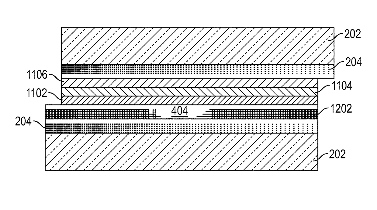
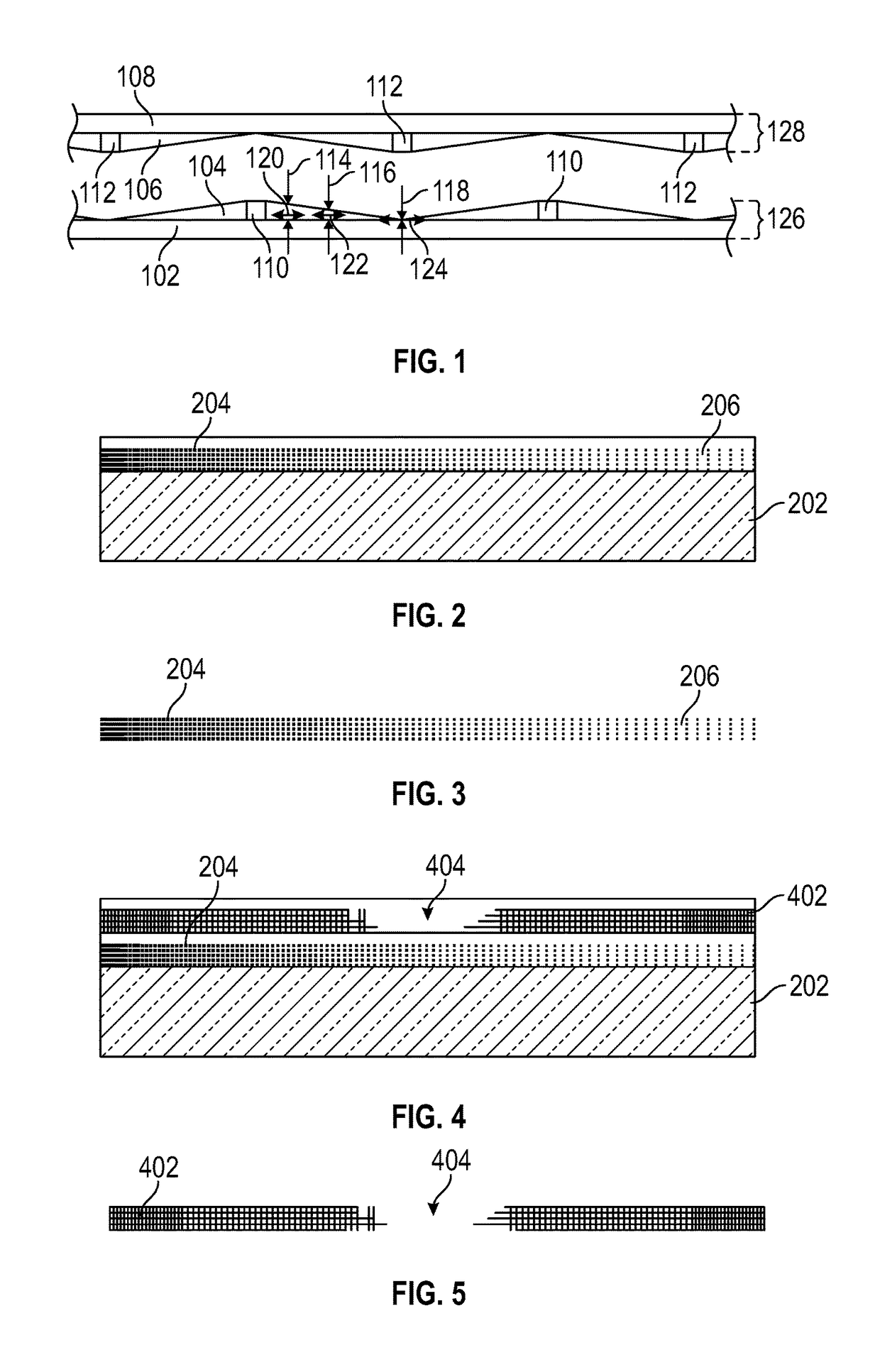
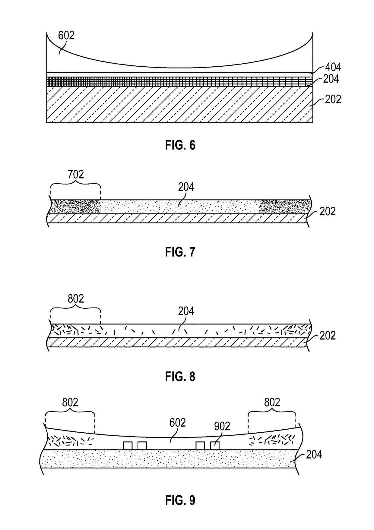
[0039]A variety of materials and manufacturing techniques are herein disclosed for making electrochromic devices, and particularly transparent conductive oxides and other transparent conductive layers, on various substrates, including flexible substrates. In some cases, these materials and manufacturing techniques are suitable for use on large or small areas of glass as a substrate, and in some cases are suitable for use on large or small areas of flexible substrates. Some examples of flexible substrates are plastic substrates made from materials such as polycarbonates, polyacrylics, polyurethanes, urethane carbonate copolymers, polysulfones, polyimides, polyacrylates, polyethers, polyester, polyethylenes, polyalkenes, polyimides, polysulfides, polyvinylacetates and cellulose-based polymers.

[0040]Transparent conductive layers with uniform horizontal sheet resistance and uniform vertical resistance are known for use in electrochromic devic...


PUM


Abstract

An electrochromic device is provided. The device includes a substrate and an electrochromic stack on the substrate. The stack includes a first set of bus bars, a first transparent conductive layer, at least one electrochromic layer, a second transparent conductive layer, and a second set of bus bars, wherein at least one of the first transparent conductive layer or the second transparent conductive layer includes resistivity that varies by horizontal location according to a resistivity profile. In some embodiments the resistivity profile has a vertical component that may or may not be in addition to the horizontal component. Various embodiments of these materials can be tuned as to profiles of vertical resistance and horizontal sheet resistance.

Description

FIELD OF THE INVENTION[0001]The present invention generally relates to switchable electrochromic devices with flexible substrates, such as for architectural windows, capable of coordinated switching over substantially their entire area or a selected subregion of their entire area. More particularly, and in one embodiment, the present invention is directed to switchable electrochromic multi-layer devices with flexible substrates, particularly for large area rectangular windows for architectural applications that switch in a spatially coordinated manner over substantially their entire area or a selected subregion of their entire area; optionally these are of non-uniform shape, optionally they switch synchronously, i.e., uniformly, over substantially their entire area or a selected subregion of their entire area, or in a coordinated but nonsynchronous manner (e.g., from side-to-side, or top-to-bottom) from a first optical state, e.g., a transparent state, to a second optical state, e.g...

Claims


Application Information

Patent Timeline
IPC IPC(8): G02F1/153G02F1/163
CPCG02F1/163G02F1/1533G02F2001/1635G02F1/155
Inventor BASS, JOHN DAVIDBERGH, HOWARD S.TIMMERMAN, NICOLASZIEBARTH, JONATHAN
Owner KINESTRAL TECH
Why Eureka
Try Eureka