Process and apparatus for the separation of the components of a liquid mixture

a technology of liquid mixture and components, which is applied in the direction of separation processes, liquid degasification, evaporation, etc., can solve the problems of low water carried in vapor, low fractionation constant, and difficult task of separation of compounds containing stable isotopes, so as to increase separation and increase the separation of components with different volatility

Active Publication Date: 2017-06-13
HYD RAKKUTATO & GYOGYSZERFEJLESZTO
View PDF13 Cites 4 Cited by
  • Summary
  • Abstract
  • Description
  • Claims
  • Application Information

AI Technical Summary

Benefits of technology

[0010]The primary object of the invention is an apparatus, able to separate components of different boiling points more efficiently than the methods available at present.
[0011]This invention is based on the recognition that by generating bubbles in the liquid to be separated to components, the liquid-vapor phase interface area can be largely increased. This area will be sufficient to allow rapid concentration of the more volatile component in the air space of the bubbles, and the liquid-vapor equilibrium at the given temperature will be reached relatively quickly. In contrast to the existing procedures (using trays, Raschig rings or an ordered packing) the invention enables to create the surface, where the components of different boiling points separate according to their fractionation constant, within the liquid phase itself. When the bubbles burst on reaching the surface of the liquid, their gas content, together with the vapor enriched in the more volatile component, goes to the space above the liquid.

Problems solved by technology

Major challenge is separation of substances with slightly different (0.5-2° C. difference) boiling point and have, hence, low fractionation constant.
Such materials can be separated only in columns of very high (theoretical or physical) plate number at considerable energy expenditure.
Separation of compound containing stable isotopes is such a difficult task.
It is a case of point, that although the fractionation constant is higher at lower temperatures, the corresponding partial vapor pressures are much lower, so at low temperatures the amount of water carried in the vapor is low which will limit productivity.
In case of manufacturing DDW or heavy water, an extra cost is incurred because stainless steel is not well wetted by water so the packing must have a phosphorous bronze finish.
The existing methods of manufacturing DDW have the following disadvantages: 1. One distillation column has low capacity, even at high energy input; 2. Operating the column at 100° C., fractionation constant is low, necessitating high plate number for attaining the theoretical maximum D level decrease, resulting in elevated investment costs; 3. Higher fractionation constant can be achieved by distilling in vacuum at a lower temperature, but the control system is then more complicated, and capacity is decreased because less water is present in the vapor phase at lower temperature; 4. Distillation columns represent high investment costs, increased further by the auxiliary equipment (high-throughput boilers, tall building for the columns, large cooling capacity).

Method used


Image

  • Process and apparatus for the separation of the components of a liquid mixture
  • Process and apparatus for the separation of the components of a liquid mixture
  • Process and apparatus for the separation of the components of a liquid mixture

Examples


example 1

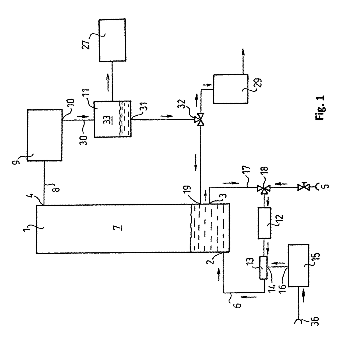
[0115]A tank of 15 L volume and 25 cm diameter is filled with 10 L water. The liquid tank (1) can be heated from below by the heat transfer unit (25) so water temperature can be set to any value. At the top of the tank (1) are connected the thermometer (but is not shown on the Figure because it is obvious) and the condenser unit (9) (a tubular heat exchanger). Liquid inlet (2) and outlet (3) are built in the side of the tank (1).

[0116]The liquid inlet (2) connects the liquid tank (1) to the liquid pump (12) which delivers water, drawn from the liquid tank (1) via the liquid outlet (3), through the bubble generator (13) and the liquid inlet (2) back to the liquid tank. A compressor (15) is connected to the bubble generator (13) and feeds it continuously with air. The required water amount is fed into the system from the liquid source (5) by the unifier-distributor unit (18). The liquid condensing at the bottom of the water-cooled condenser unit (9) goes to the collector tank (11) whi...

example 2

[0119]Using the above prototype but running it at 80° C., the decrease of D content in the produced water was only 4.6 ppm. This showed that separation worsens with increasing temperature, proving the correctness of the theoretical background of the invention.

example 3

[0120]An apparatus set up from the elements in example 1, but modified as follows:

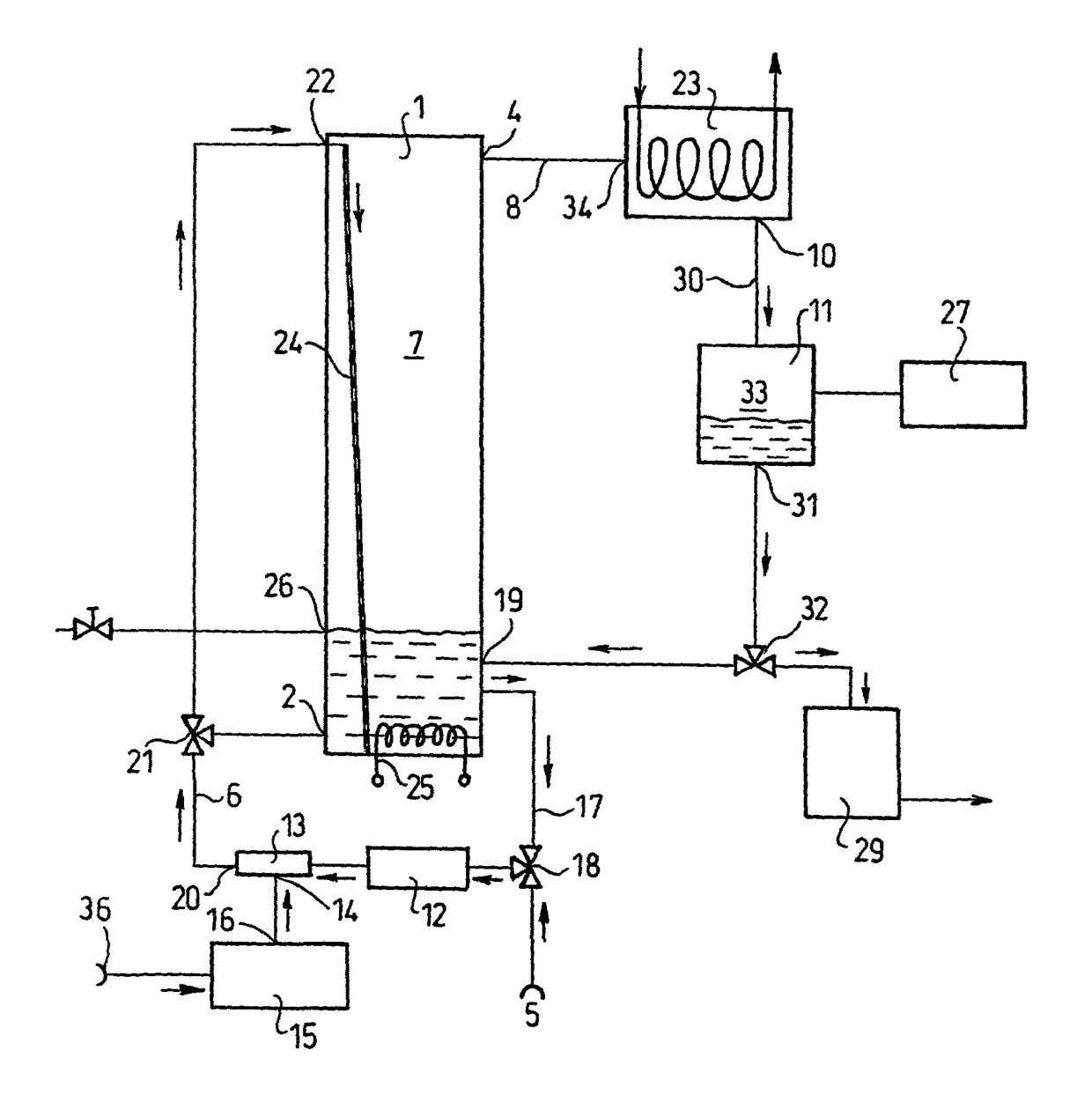
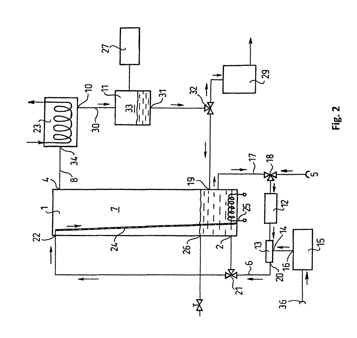
[0121]The liquid tank is 1 m high, 25 cm in diameter and contains 15 L water. The pipe leaving the bubble generator (13) is bifurcated in the distributor unit (21). One line delivers (as in example (1) bubble-saturated water to the bottom of the liquid tank (1) through liquid pump (12) and liquid inlet (2). The other line goes to the liquid inlet (22) arranged in the upper part of the liquid tank (1), and the bubble-saturated water flows down spreading on the wall of the tank, or down an extra surface-enlarging unit (24), expediently a sieve-like surface, to the bottom of the tank. The distributor unit (21) before the bifurcation regulates in what proportion the bubble-saturated water delivered by the liquid pump (12) goes to the two branches. This construction ensures that the bubbles leave the water flowing on the wall of the liquid tank (1) and so the amount of evaporated water is greatly increased....


PUM

PropertyMeasurementUnit
diameteraaaaaaaaaa
boiling pointaaaaaaaaaa

Abstract

Process and apparatus for the separation of the components having different boiling points of a liquid mixture, characterized in that forming bubbles by a carrier gas in the liquid mixture where the one or more volatile component is getting enriched in the bubbles, then after said bubbles leave the liquid phase the released vapor content of them is collected and condensed and the obtained liquid being enriched in the more volatile component(s) is separated from the carrier gas.

Description

[0001]This is the national stage of International Application PCT / HU2012 / 000069, filed Aug. 13, 2012.[0002]The invention relates to an apparatus and process for separation and concentration of liquids with different boiling point.PRIOR ART[0003]Fractional distillation has been used in the industry for decades to separate substances of different boiling point. Separation of alcohol from water, or obtaining mineral oil products of boiling points are well-known examples. In both, the difference in the boiling points of the components to be separated is large, up to several tens of degrees centigrade (° C.), so separation by fractional distillation is relatively easy and economical—what shows that alcohol, and oil derivatives, produced this way are manufactured and used in the order of million tons per year. Major challenge is separation of substances with slightly different (0.5-2° C. difference) boiling point and have, hence, low fractionation constant. Such materials can be separated...

Claims


Application Information

Patent Timeline
Patent Type & Authority Patents(United States)
IPC IPC(8): B01D1/14B01D1/00B01D19/00B01D59/04B01D5/00B01D3/00B01D59/22
CPCB01D19/0005B01D1/007B01D1/14B01D3/008B01D5/006B01D59/04B01D59/22
Inventor SOMLYAI, GABOR
Owner HYD RAKKUTATO & GYOGYSZERFEJLESZTO
Why Eureka
Try Eureka