
Phosphor, light emitting element, and light emitting device

a light emitting element and phosphor technology, applied in the direction of semiconductor devices, luminescent compositions, chemistry apparatus and processes, etc., can solve the problems of difficulty in achieving high luminance and poor color rendering properties of white leds, and achieve high color rendering properties and color reproducibility, superior moisture resistance, and long life span

Active Publication Date: 2017-06-13
DENKA CO LTD
View PDF23 Cites 0 Cited by
  • Summary
  • Abstract
  • Description
  • Claims
  • Application Information

AI Technical Summary

Benefits of technology

The present invention is related to a phosphor that is resistant to moisture and has superior properties in terms of color rendering and color reproduction. This phosphor is also long-lasting and has minimal changes over time. The technical effects of this invention are its improved performance and durability in light emitting elements and devices.

Problems solved by technology

In other words, such white LEDs have poor color rendering properties which are an indicator of the naturalness of appearance of objects.
However, phosphors in which Eu2+is activated as the light emission central ion have a light emission spectrum with a broad half value width, so they have a tendency to include relatively many spectral components in wavelength regions outside the range visible to humans, and they have difficulty in achieving high luminance.

Method used


Image

  • Phosphor, light emitting element, and light emitting device
  • Phosphor, light emitting element, and light emitting device
  • Phosphor, light emitting element, and light emitting device

Examples


example 1

[0071]20 g of the phosphor of Comparative Example 1 were added to 100 ml of a mixed solution (volume ratio 1:1) of hydrofluoric acid having a concentration of 20% and methanol to prepare a suspension.

[0072]While stirring this suspension, 25 ml of an aqueous solution of calcium chloride having a concentration of 0.6 mol % were added. After addition, the suspension was further stirred for 10 minutes. After the stirring ended, the suspension was let stand to allow the phosphor to settle, and the operation of removing the supernatant, adding methanol thereto, stirring and allowing to stand, then removing the supernatant and further adding methanol was repeated until the solution became neutral.

[0073]Thereafter, the precipitated particles were recovered by filtration, and further dried to completely remove the methanol by evaporation, resulting in the phosphor of Example 1.

examples 2 to 4

[0074]Examples 2, 3 and 4 were produced using entirely the same methods and conditions as Example 1, except that the concentration of the aqueous solution of calcium chloride added to the phosphor suspension was changed respectively to 0.3 mol %, 0.8 mol % and 1.2 mol %.

examples 5 to 8

[0075]Examples 5 to 8 were produced using entirely the same methods and conditions as Example 1, except that the concentration of the aqueous solution of calcium chloride added to the phosphor suspension was changed respectively to 0.7 mol %, 0.2 mol %, 0.5 mol % and 1.4 mol %.

[0076]Next, the resulting phosphors were evaluated by the following method.

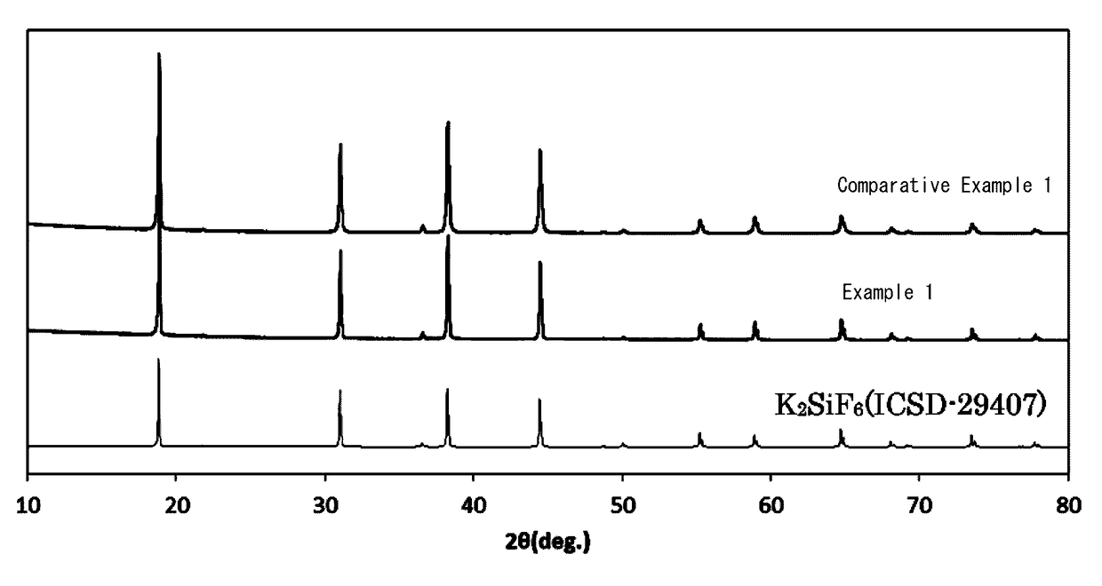
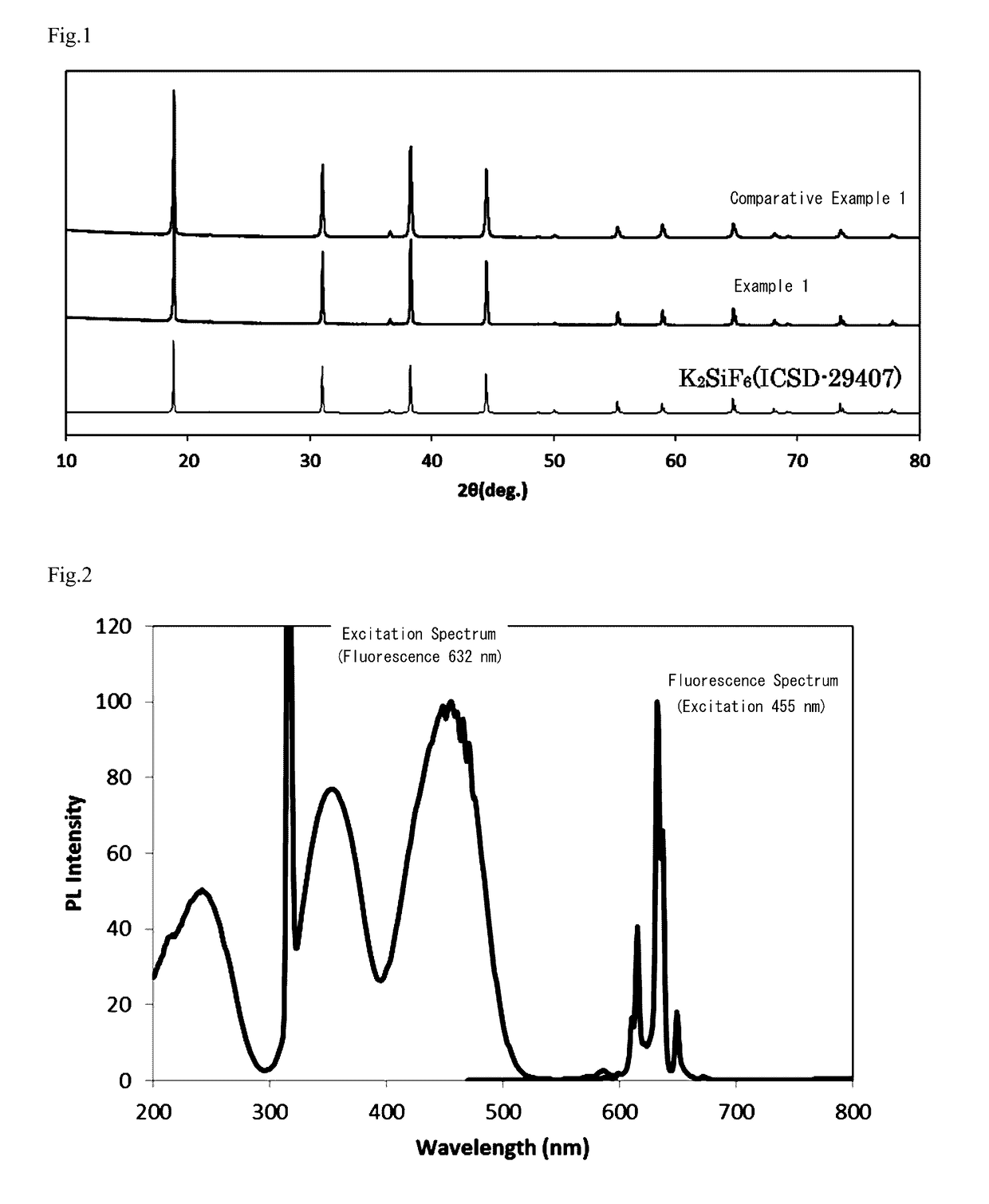
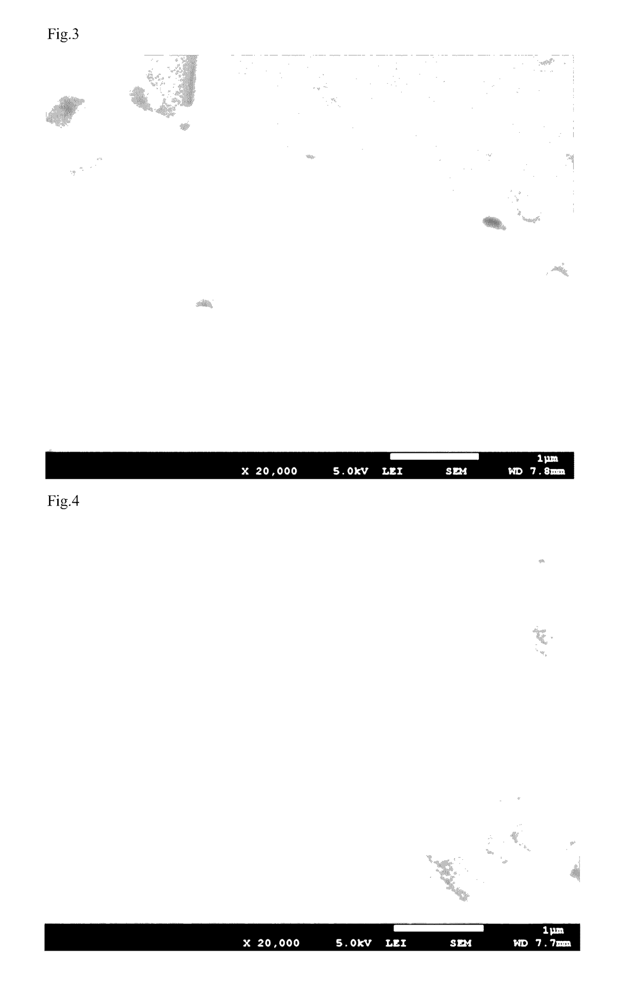
[0077]First, the phosphors of Comparative Example 1 and Examples 1 to 4 were evaluated as to their crystal phases, excitation spectrum / fluorescence spectrum, quantum efficiency, chromaticity coordinates, atomic composition ratio Ca / (K+Ca), surface structure and moisture resistance. The evaluation results are shown in Table 1 and FIGS. 1 to 4.

[0078]

TABLE 1Optical Properties (excitation 455 nm)ExternalQuantum Effic.Atomic(%)Comp.InternalHi-Temp.CaClChromaticityRatioCaQuantumHi-Humid.Moist.Conc.Coordinates(Ca / DepthAbsorp.Effic.TreatmentResist.(mol %)xy(K + Ca))(μm)(%)(%)beforeafterEval.Comp.—0.6910.3070—7485635079%Ex. 1Ex. 10.60.6910.3070....


PUM

PropertyMeasurementUnit
depthaaaaaaaaaa
depthaaaaaaaaaa
depthaaaaaaaaaa

Abstract

The present invention relates to an Mn4+-activated complex fluoride phosphor with improved moisture resistance due to modification of the particle surface, and a light emitting element and light emitting device having excellent color rendering properties and stability due to the use of this phosphor.The phosphor of the present invention is characterized in that it is represented by the general formula: A2MF6:Mn4+, wherein element A is an alkali metal element comprising at least K, element M is one or more metal elements chosen from among Si, Ge, Sn, Ti, Zr and Hf, F is fluorine, and Mn is manganese, wherein the phosphor comprises a Ca-containing compound on a particle surface.

Description

TECHNICAL FIELD[0001]The present invention relates to a phosphor that is excited by UV rays or blue light and emits red light, a light emitting element using this phosphor, and a light emitting device using this light emitting element. More specifically, the present invention relates to an Mn4+-activated complex fluoride phosphor with improved moisture resistance due to modification of the particle surface, and a light emitting element and light emitting device having excellent color rendering properties and stability due to the use of this phosphor.BACKGROUND ART[0002]As white LEDs, those of the type in which pseudo-white light is obtained by combining a blue LED chip with a yellow phosphor are widely used. However, while white LEDs of this type fall within the white color range in terms of their chromaticity coordinate values, they have few emitted light components in the red color range and the like, so the appearance of an object illuminated by such a white LED differs considera...

Claims


Application Information

Patent Timeline
Patent Type & Authority Patents(United States)
IPC IPC(8): H01L33/50C09K11/61
CPCH01L33/502C09K11/617H01L33/50H01L33/501C09K11/57C09K11/61
Inventor EMOTO, HIDEYUKIYANAGI, SHINICHIICHIKAWA, MASAYOSHIITO, KAZUHIRO
Owner DENKA CO LTD
Learn More