
Method and system for computing reference signals for machines with redundant positioning

a reference signal and machine technology, applied in the direction of electric programme control, program control, instruments, etc., can solve the problems of slow dynamic speed, limited stroke range, and inability to ensure the constraints are met, so as to avoid undesirable vibration of mechanical components and increase the throughput of machines

Active Publication Date: 2017-07-04
MITSUBISHI ELECTRIC RES LAB INC
View PDF24 Cites 1 Cited by
  • Summary
  • Abstract
  • Description
  • Claims
  • Application Information

AI Technical Summary

Benefits of technology

This patent aims to improve the performance of a laser cutting machine by allowing the laser spot to follow the path with the highest possible velocity. This increases the throughput of the machine. The positioning subsystems should provide reference trajectories that are as smooth as possible to avoid vibrations of the mechanical components. The smoothness means that the reference trajectories have a minimal jerk, which is the third derivative of the position with respect to time.

Problems solved by technology

These machines also have constraints associated with the actuators such as stroke limits, velocity limits, and torque limits.
This is an ad hoc method that does not provide any guarantee that the constraints are satisfied for all the possible operating conditions of the machine.
The fine positioner has a faster dynamics but is limited by its small stroke range.
However, in the absence of such feasible trajectory the control system may fail to compute a trajectory that satisfies all of the constraints.
None of the conventional methods for the control of redundant positioning systems have managed to address the problem of computing reference trajectories that guarantee constraint satisfaction.
But this is undesirable because the system performance, e.g., throughput, is dependent on these gains and filter frequencies.
Furthermore, regardless of the gain magnitudes and the filter frequencies, constraint satisfaction is not guaranteed for all the different desired motion of the machine.
In addition, tuning the filter gains, the delay elements, the limiters, and the dead-band elements is a task for which no systematic procedure is available, and hence can be time consuming, error prone, and may result in the reduced machine performance, in terms of throughput and precision.

Method used


Image

  • Method and system for computing reference signals for machines with redundant positioning
  • Method and system for computing reference signals for machines with redundant positioning
  • Method and system for computing reference signals for machines with redundant positioning

Examples


Embodiment Construction

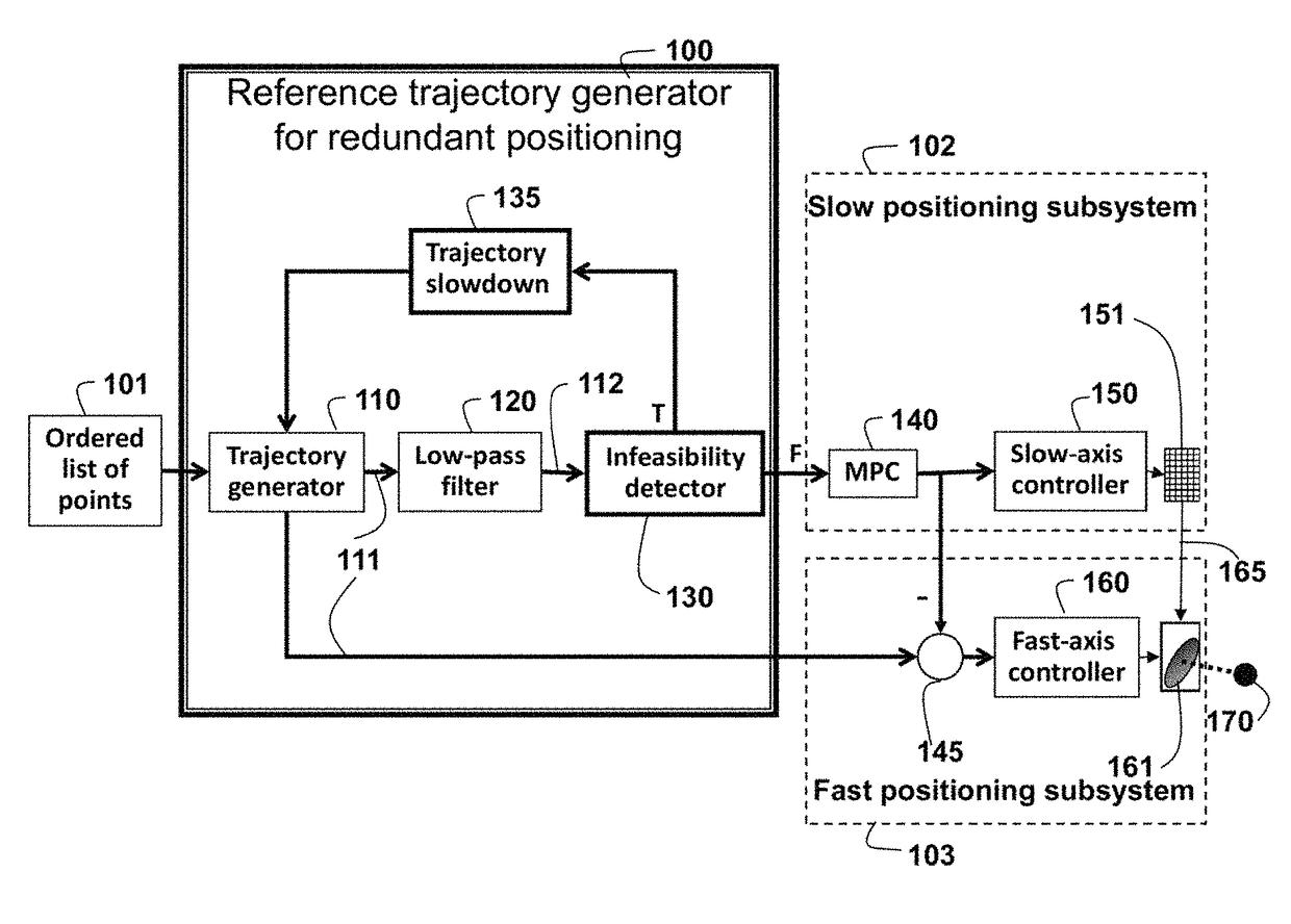
[0033]As shown schematically in FIG. 1, the embodiments of the invention provide a system and method 100 for generating reference trajectories for positioning machines with redundant actuators, e.g., a laser drilling system. It is understood that the invention can be applied too other types of positioning systems with redundant actuators.

[0034]In particular, we have described embodiments using a redundant laser drilling system, but the invention has the same effect for a processing machine such as a redundant laser cutting system, a redundant laser marking system, a redundant scribing system, a redundant laser direct imaging system or a redundant electron beam processing machine.

[0035]The overall system includes the reference trajectory generator 100, a slow positioning subsystem 102 and a fast positioning subsystem 103. Depending on components selected, such as linear actuators and galvano mirror assemblies, the velocity of the fast positioning system is about one order of magnitud...


PUM


Abstract

A method computes reference signals for a machine with redundant positioning by first generating a reference trajectory according to an ordered list of points. Then, using a filter or by choosing the value of the reference at each sampling time, a reference trajectory for the slow subsystem is produced. Next, determine whether the reference trajectory and the slow subsystem reference trajectory violate feasibility constraints, and if true, slowing down the reference trajectory and repeating with the generation of the slow subsystem reference trajectory. The slow subsystem reference trajectory is sent, via a model predictive control block, to a slow positioning subsystem controller, and a combination of the slow subsystem reference trajectory and the reference trajectory is sent to a fast positioning subsystem controller.

Description

FIELD OF THE INVENTION[0001]This invention relates generally to coordinated control of machines with redundant actuators for positioning, and more particularly to machines and subsystems that are subjected to physical and operational constraints.BACKGROUND OF THE INVENTION[0002]Positioning systems with redundant actuators are widely used in manufacturing and factory automation. In these machines, multiple actuators are available along each axis of motion such that the machine position state is a function (often a sum) of each individual actuator state. In some cases, the states of the entire system can be represented by a linear combination of individual positions of the positioning subsystems.[0003]These machines also have constraints associated with the actuators such as stroke limits, velocity limits, and torque limits. These constraint must be satisfied during operation. Approaches to controlling redundant positioning machines with constraints range from simple ad hoc gain tunin...

Claims


Application Information

Patent Timeline
Patent Type & Authority Patents(United States)
IPC IPC(8): G06F19/00G05B19/19
CPCG05B19/19G05B19/195G05B2219/41105G05B2219/41194G05B2219/42089G05B2219/42219G05B2219/45041G05B2219/45139G05B2219/50047
Inventor HAGHIGHAT, SOHRABDI CAIRANO, STEFANOBORTOFF, SCOTT A.
Owner MITSUBISHI ELECTRIC RES LAB INC
Learn More