Reamer shoe attachment for flexible casing shoe

a flexible casing and shoe technology, applied in the field of downhole tools, can solve the problems of tubing end being subject to wear and damage, tubing end being subject to irregularities and restrictions in the bore wall, tubing end being easy to be broken up, etc., to achieve the effect of enhancing drillability, reducing density, and facilitating breakag

Active Publication Date: 2017-07-11
WWT NORTH AMERICA HLDG
View PDF22 Cites 2 Cited by
  • Summary
  • Abstract
  • Description
  • Claims
  • Application Information

AI Technical Summary

Benefits of technology

[0007]The present invention is directed to a reamer shoe attachment for a flexible casing shoe having ceramic inserts, made from silicon nitride and / or aluminum oxide. Silicon nitride and aluminum oxide are harder than most rock materials, but are far lower in density than tungsten carbide material normally used as a reamer shoe. Silicon nitride and aluminum oxide are far easier to be broken up and flushed harmlessly out of the hole when it is required to drill through the reamer when drilling the next wellbore section. In addition, these materials can be broken up if needed using PDC and tungsten carbide which enhances their drillability.
[0008]The ceramic inserts are held in the reamer body using a metallic framework or cage to locate the inserts and provide a load bearing structure to support the loads and conduct heat away from the inserts. The framework is preferably made of a strong and light aluminum alloy, but also could be made using steel. The framework and inserts can be cast into the body using anyone of several open casting methods using liquid materials that solidify to faun a solid structure. The inserts for the reamer shoe could reside in narrow ribs on the outside diameter of the reamer shoe, with wider ribs included to limit the depth of the cuts so that the cutting surfaces are not overloaded. Narrow and wider rib designs also ensure that drilling fluid is guided past the inserts to cool them and transport cuttings uphole.
[0009]The reamer shoe could be placed at the front end of a flexible casing shoe, or could form an integral part of the flexible casing shoe. The flexible casing shoe is a short, 20 to 500 foot, guiding section in front of the casing which has a lower stiffness than the casing. The guiding section is a cylindrical or tubular guide in front of the casing that has stiffness that is about 5% to about 80% and more preferably about 5% to about 25% of the stiffness of the casing being run. The lower stiffness of the leading cylindrical or tubular guide section allow it to more easily deflect and travel down the intended wellbore without causing undue stress on the formation. Once the lower stiffness section has entered the curve portion of a wellbore, it would be able to distribute the additional bending force required to deflect the higher stiffness casing behind it and therefore prevent the casing from digging in the wellbore and rock formations.

Problems solved by technology

As the tubing is run into the bore, the tubing end will encounter irregularities and restrictions in the bore wall, for example ledges formed where the bore passes between different formations and areas where the bore diameter decreases due to swelling of the surrounding formation.
Further, debris may collect in the bore, particularly in highly deviated or horizontal bores.
Accordingly, the tubing end may be subjected to wear and damage as the tubing is lowered into the bore.
Another problem encountered is the difficulty of running casing through build sections.
More specifically, there is difficulty in running large diameter casing through the build section of a well in moderate to soft formations.
The problem with PDC inserts is that they are expensive, and are made by bonding a layer of diamond to tungsten carbide.
Tungsten carbide is very hard, abrasive and most importantly has a very high density.
This means the reamer will be difficult to drill, and when it is drilled through, the tungsten carbide pieces are going to reside in the bottom of the well and because of their high density precludes them from being flushed out of the hole through normal circulation.
In horizontal and directional wells, these pieces can cause wear and damage to other steel downhole components during further drilling operations.

Method used


Image

  • Reamer shoe attachment for flexible casing shoe
  • Reamer shoe attachment for flexible casing shoe
  • Reamer shoe attachment for flexible casing shoe

Examples


Embodiment Construction

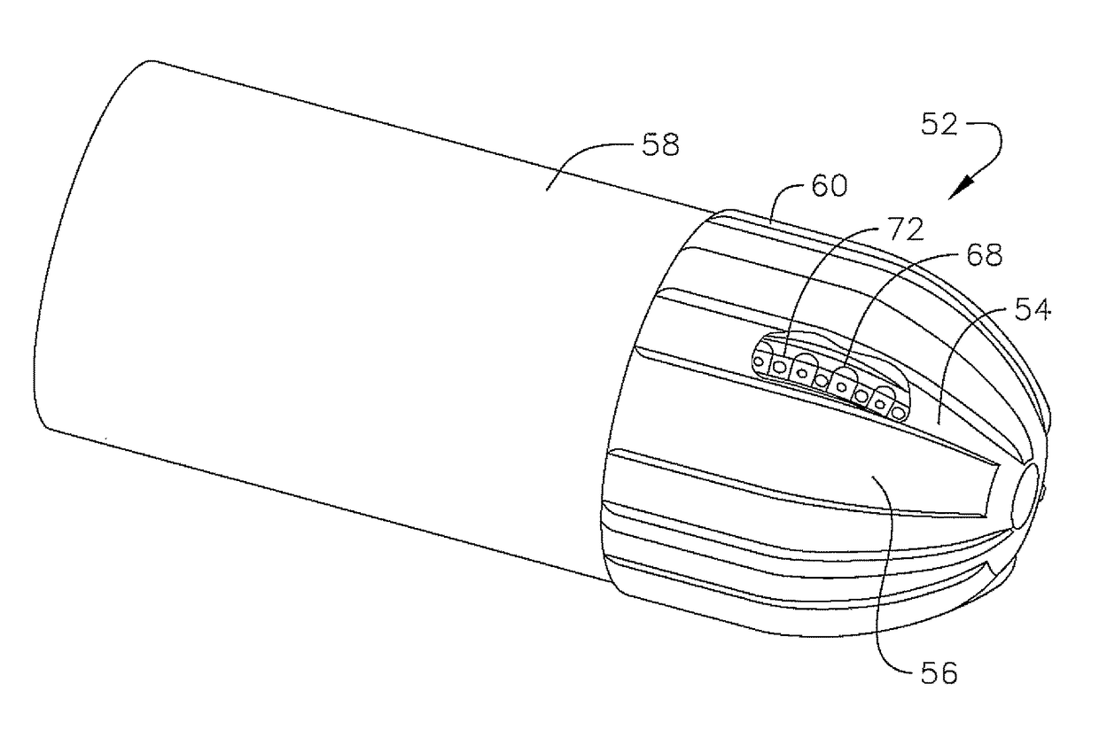
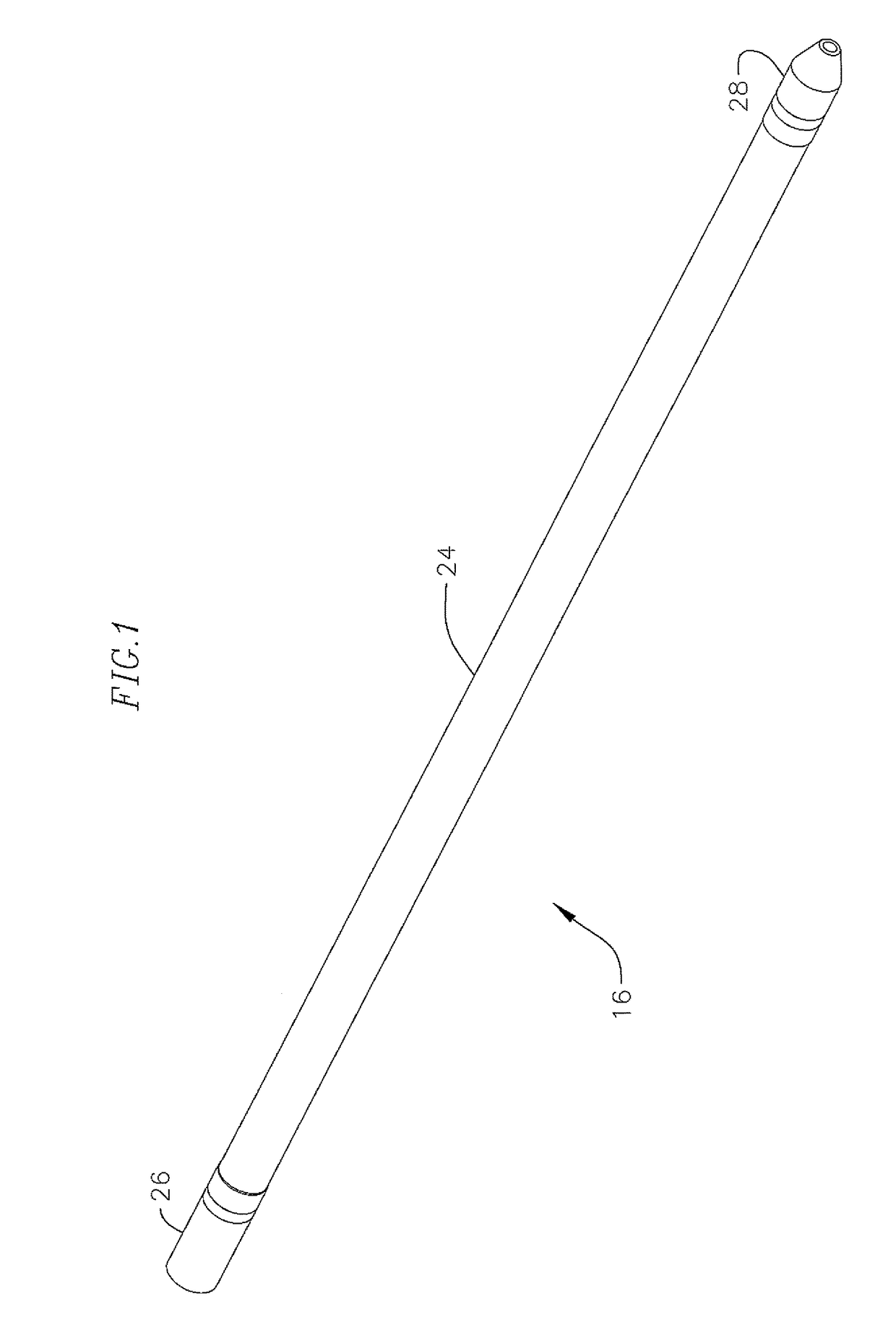
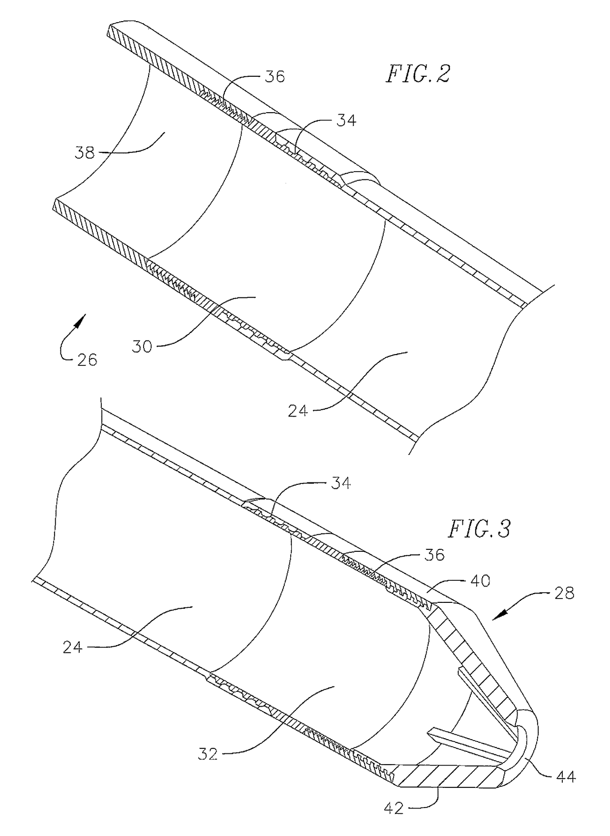
[0017]Running normal wellbore casing requires a large deflection force at the leading edge and to reduce the force required to deflect the casing and allow the leading edge or shoe to follow the casing in the wellbore, a flexible casing guide 16 as shown in FIG. 1 is positioned at the leading edge of the casing. The flexible casing guide 16 requires less force to deflect and therefor follow the curve section of the wellbore. The length and stiffness of the flexible casing guide distributes the normal casing deflection force thereby reducing the risk of sticking the casing through a curved wellbore section. The flexible casing guide 16 can be a short cylindrical guide section, for example from about 20 to about 500 feet long, extending from an end of the normal casing and has a lower stiffness than the casing. The lower stiffness of the casing guide is about 5% to about 80%, and more preferably about 5% to about 25% of the stiffness of the casing. The lower stiffness of the leading c...


PUM


Abstract

A drillable reamer shoe having a reamer body and a nose section having a metallic cage containing a plurality of ceramic inserts made from silicon nitride or aluminum oxide. The drillable reamer shoe is positioned on an end of a flexible wellbore casing guide comprising a tubular body having a stiffness lower than a wellbore casing.

Description

CROSS-REFERENCE TO RELATED APPLICATION(S)[0001]This application claims priority to and the benefit of U.S. Provisional Application No. 61 / 985,990, filed Apr. 29, 2014 the contents of which are incorporated herein by reference.BACKGROUND[0002]The present invention is directed to a downhole tool, and more particularly to a reamer shoe attachment for a flexible casing guide running tool.[0003]In oil and gas exploration and production operations, bores are drilled to gain access to subsurface hydrocarbon-bearing formations. The bores are typically lined with steel tubing, known as tubing, casing or liner, depending upon diameter, location and function. The tubing is run into the drilled bore from the surface and suspended or secured in the bore by appropriate means, such as a casing or liner hanger. For a casing, cement may then be introduced into the annulus between the tubing and the bore wall.[0004]As the tubing is run into the bore, the tubing end will encounter irregularities and r...

Claims


Application Information

Patent Timeline
Patent Type & Authority Patents(United States)
IPC IPC(8): E21B10/26E21B17/20E21B17/14
CPCE21B10/26E21B17/14E21B17/20
Inventor MITCHELL, SARAH
Owner WWT NORTH AMERICA HLDG
Why Eureka
Try Eureka