Device and method for the nondestructive testing of tires by tomography

Active Publication Date: 2017-07-11
CYXPLUS
View PDF4 Cites 2 Cited by
  • Summary
  • Abstract
  • Description
  • Claims
  • Application Information

AI Technical Summary

Benefits of technology

[0006]In this context, the aim of the present invention is to propose a device and a method for inspecting tires by tomography, free of at least one of the limitations described previously and, in particular, which make it possible, with a reduced cycle time, to r

Problems solved by technology

This calibration is a lengthy operation which requires the inspection of a reference part of perfectly known ge

Method used


Image

  • Device and method for the nondestructive testing of tires by tomography
  • Device and method for the nondestructive testing of tires by tomography
  • Device and method for the nondestructive testing of tires by tomography

Examples


Embodiment Construction

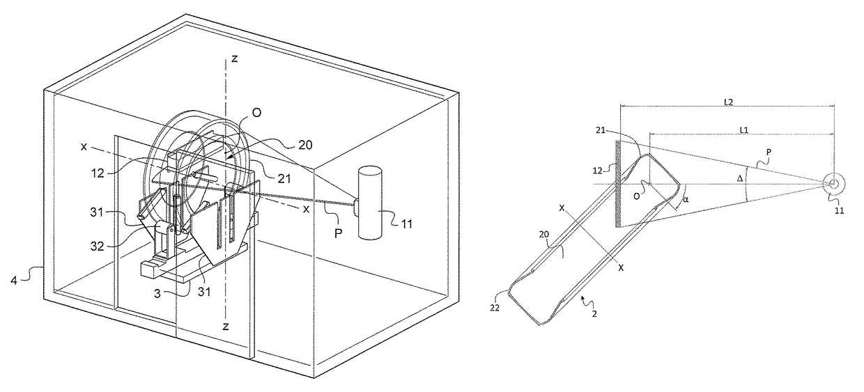
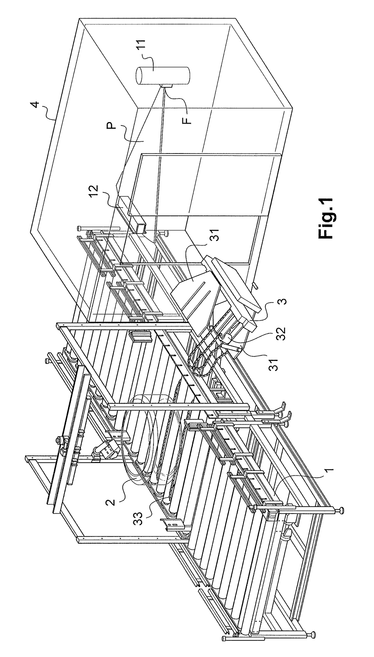
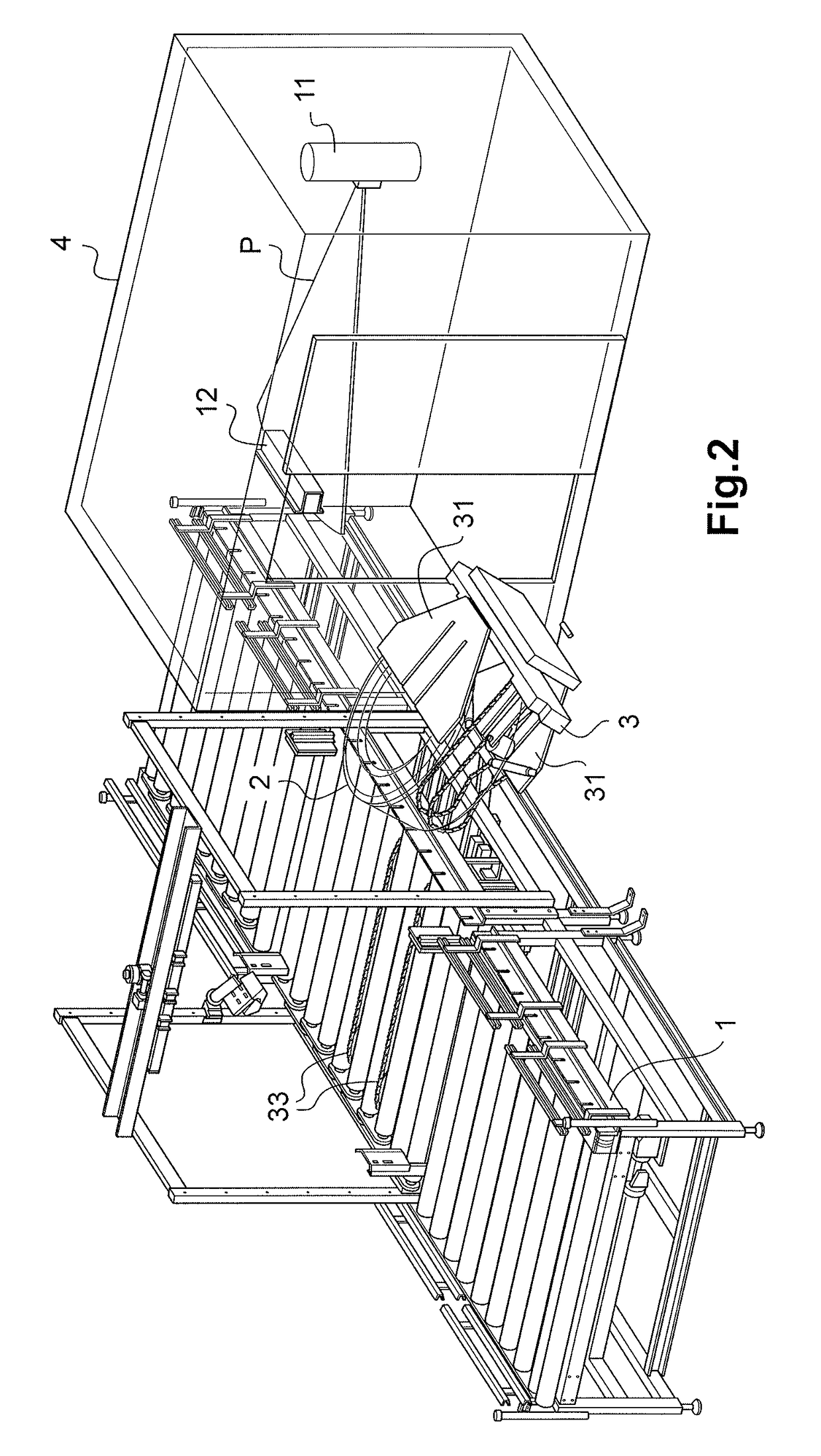
[0041]The device according to the invention for inspecting tires by X-ray tomography is intended to be incorporated in a tire production line. A feed conveyor 1 for a tire 2 cooperates with a handling carriage 3 to transfer the tire 2 from the feed conveyor 1 to an inspection chamber 4, having walls impermeable to the X-rays, where an X-ray source 11 and an X-ray detector 12 are arranged. The detector 12 can be a linear or matrix detector and is arranged horizontally in the inspection chamber 4 facing the source 11. The source 11 is preferentially equipped with a collimator such that the radiation is emitted in the form of a flat beam of horizontal axis, defining a sectional plane P, also called firing plane, passing through the focus F of the source 11 and the detector 12, positioned horizontally.

[0042]The handling carriage 3 of the tire comprises a frame supporting a motor-drive system making it possible for the carriage 3 to be able to be displaced on a rail (not represented) arr...


PUM


Abstract

A device for testing a tyre (2) for representing tomographical images of sections of a casing of the tyre includes a source (11) of ionizing radiation arranged outside the tyre (2) and a detector (12) for receiving the radiation. The detector (12) is situated opposite the source (11) with respect to at least one section of the casing. The axis (X-X) of the tyre runs parallel to a sectional plane (P) passing through the focus (F) of the source (11) and the detector (12). The tyre and the source-detector assembly are moved with rotational motion relative to one another about an axis of rotation (Z-Z) perpendicular to the sectional plane (P), according to a predetermined angular excursion range. The detector (12) is disposed in a central internal zone (20) of the tyre (2) during the testing cycle.

Description

CROSS-REFERENCE TO RELATED APPLICATIONS[0001]The present application is a 35 U.S.C. §§371 national phase conversion of PCT / FR2014 / 050198, filed Feb. 4, 2014, which claims priority of French Patent Application No. 1350955, filed Feb. 4, 2013, the contents of which are incorporated by reference herein. The PCT International Application was published in the French language.[0002]The present invention relates to a tomographic inspection method based on X-ray exploration of a tire, with a view to a non-destructive inspection of its internal structure. It relates also to a device for implementing this method. The method and the device allow for the representation of tomographic images of slices of tires.[0003]As is known, obtaining a tomographic image of a section of an object using a tomographic apparatus including a source-detector assembly comprises emitting a beam of incident X-rays toward this object, while the detector measures the absorption of the X-rays passing through the object...

Claims


Application Information

Patent Timeline
IPC IPC(8): G01N23/02G01M17/03G21K1/02G01N23/18
CPCG01N23/185G01M17/028G21K1/02G01N2223/627G01N23/083
Inventor DECROUX, AGNESFICALORA, FABRICEROUBAUD, OLIVIERFRANCOIS, OLIVIER
Owner CYXPLUS
Why Eureka
Try Eureka