Ultra sagging and melting resistant fin material with very high strength

a technology applied in the field of ultra-sagging and melting resistance fin materials, can solve the problems of insufficient properties of aluminium strips for certain applications, and achieve the effects of high sagging resistance, excellent brazing performance, and high strength

Active Publication Date: 2017-07-25
GRAENGES SWEDEN AB
View PDF23 Cites 5 Cited by
  • Summary
  • Abstract
  • Description
  • Claims
  • Application Information

AI Technical Summary

Benefits of technology

[0008]The object of the present invention is an aluminium strip, which after brazing have a very high strength combined with excellent brazing performance, described as a high sagging resistance and a very low susceptibility to liquid core penetration during brazing, as well as good forming properties in the as delivered strip condition. The strip is mainly intended for thin clad fin applications in heat exchangers produced by CAB brazing, but can also be produced by vacuum brazing.
[0014]The material obtained according to the present invention has got a very high strength after brazing in a unique combination with excellent brazing performance like a high sagging resistance and a very low susceptibility for liquid core penetration during brazing and a good formability in the delivery temper. In particular this material is unique when used for thin clad fin applications. The fin material has a corrosion potential that may be adjusted, by controlled additions of zinc, to other parts of the heat exchanger like tubes so that the tubes can be protected by a sacrificial fin material. The material may be used to make products by any brazing method, in particular the controlled atmosphere brazing method (CAB).

Problems solved by technology

Previously known methods do however often result in insufficient properties of the aluminium strip for certain applications when the manufacturers need to down gauge, especially when using slow braze cycles.

Method used


Image

  • Ultra sagging and melting resistant fin material with very high strength
  • Ultra sagging and melting resistant fin material with very high strength
  • Ultra sagging and melting resistant fin material with very high strength

Examples


example 1

[0049]Braze simulations using different brazing cycles were performed on the above materials.

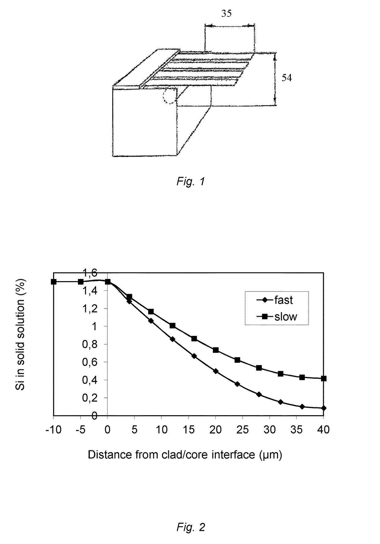
[0050]Samples were formed as fins and brazed on unclad AA3003 plates after fluxing. Two different brazing cycles were tested in order to simulate different speeds in brazing cycles as shown in Table 2 and FIG. 4. The dark curve shows the fast cycle and the light curve the slow cycle corresponding to a typical condenser brazing cycle. The brazed samples were cross sectioned and studied. The quality of the joints was graded and the amount of filler penetrating the core was evaluated (see Table 3). The amount of filler metal penetrations found were graded as: Many or Few.[0051]In cycle Slow the 50LSi material had fewer areas with filler metal core penetration than the 50MSi material.[0052]In the 70LSi and 70MSi materials very few areas were found with filler metal inside the fin cores.[0053]In the 70MSi material many areas with filler metal core penetration was fond.

[0054]Filler metal penetrati...

example 2

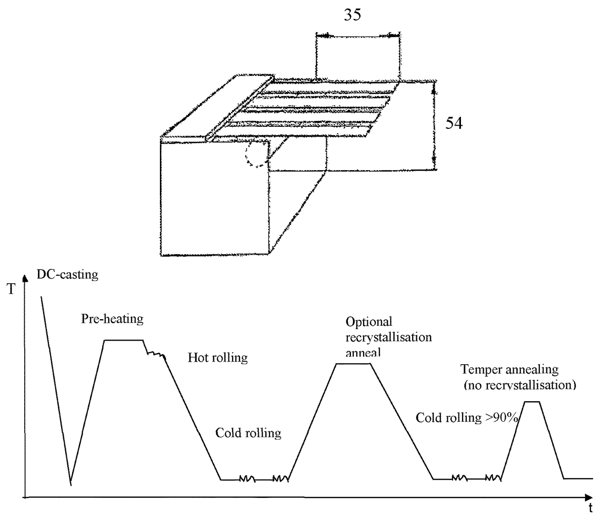
[0057]The sagging resistance of samples braze simulated according to Slow braze cycle was measured according to the following method: The material is mounted in a special rig as shown in FIG. 1. Samples 15 mm wide were cut across the rolling direction and at least 90 mm along the rolling direction. Four samples were mounted in the rig. The cantilever beam length was 35 mm, and the free end of the cantilever was 54 mm above the surface of the measuring table.

[0058]The rigs were placed in the oven and the temperature was raised according to braze cycle Slow. The samples were removed immediately after the last soak at 600° C.

[0059]The sagging resistance of the material with 0.16% Si showed to be much better than the sagging resistance of the reference sample containing 0.5% Si, table 4.

[0060]

TABLE 4Sagging, beam length 35 mmThicknessSagging(μm)(mm)50LSi49650MSi5127

example 3

[0061]Tensile testing was performed in delivery condition and after braze simulation using brazing cycle Fast see Table 5. The result shows that the highest strength for a given thickness in the delivery condition is obtained for the samples with a low Si content.

[0062]

TABLE 5Result from tensile testing on samples taken from the middle of the strip before andafter braze simulationDelivery conditionAfter braze simulationGaugeRp0.2RmA50 mmGaugeRp0.2RmA50 mmSample(mm)(MPa)(MPa)(%)(mm)(MPa)(MPa)(%)50LSi0.05115817360.04872158450MSi0.05114416880.04873157470LSi0.07017419090.06766161670MSi0.06916218370.06673175570HSi0.0691801921.30.067541559


PUM

PropertyMeasurementUnit
temperatureaaaaaaaaaa
diameteraaaaaaaaaa
thicknessaaaaaaaaaa

Abstract

Method for producing AIMn strip or sheet for making components by brazing and products obtained by said method, in particular fin materials of thin gauge used in heat exchangers. Rolling slabs are produced from a melt with <0.3% Si, ≦0.5% Fe, ≦0.3% Cu, 1.0-2.0% Mn, ≦0.5% Mg, ≦4.0% Zn, ≦0.5% Ni, ≦0.3% each of group IVb, Vb, or Vib elements, and unavoidable impurity elements, as well as aluminum that, prior to hot rolling, are preheated at <550° C. to control the number and size of dispersoid particles, hot rolled into a hot strip, cold rolled into a strip with total reduction of at least 90%, and heat treated to obtain a 0.2% proof stress value that is 50-90% of its proof stress value in the as cold rolled condition and in a range between 100 and 200 MPa. The strip may alternatively be produced by twin-roll strip casting.

Description

RELATED APPLICATIONS[0001]The present application is a U.S. National Phase Application of International Application No. PCT / SE2013 / 050589, filed 23 May 2013, which claims priority to Swedish Application No. 1250528-5, filed 23 May 2012.BACKGROUND[0002]The present invention relates to a method for producing AIMn strip or sheet for producing components by brazing, as well as the products obtained by said method. In particular this method is related to fin materials used in heat exchangers.[0003]A challenge today is to manufacture light-weight components for the automotive market. A lot of research is therefore directed to reduce the weight of heat exchangers by using thinner strip without sacrificing, but instead often improving, other product and manufacturing properties. To be able to do this it is necessary to create new materials with higher post braze strength compared to the alloys presently used but still with adequate corrosion properties. For fins this means that they normall...

Claims


Application Information

Patent Timeline
Patent Type & Authority Patents(United States)
IPC IPC(8): C22C21/00B23K35/02C21D8/02C22C21/02F28F21/08B23K35/28B22D21/00F28F19/00B22D11/00B32B15/01B22D11/06C22F1/043C22F1/04F28F1/10
CPCF28F21/084B22D11/003B22D11/0622B22D21/007B23K35/0238B23K35/286B32B15/011C21D8/02C21D8/0226C21D8/0236C22C21/00C22C21/02C22F1/04C22F1/043F28F19/004C21D2251/02F28F1/10Y10T428/12063B22D11/00B32B15/016
Inventor OSKARSSON, ANDERS
Owner GRAENGES SWEDEN AB
Why Eureka
Try Eureka