Optical spatial-division multiplexed transmission system and transmission method

a spatial division and transmission system technology, applied in multiplex communication, channel dividing arrangement, baseband system details, etc., can solve the problems of insufficient long-haul applications, high complexity of the transmission system, and increase the transmission capacity of the system, so as to improve the accuracy, cost and size of the skew detection system. , the effect of improving the transmission characteristics

Active Publication Date: 2017-08-08
NEC CORP
View PDF9 Cites 0 Cited by
  • Summary
  • Abstract
  • Description
  • Claims
  • Application Information

AI Technical Summary

Benefits of technology

[0017]Therefore there is a need for improvement of transmission characteristics for SDM signals and to compensate skew as well as skew variations between SDM channels, for improvement in the precision, cost and size of skew detection systems for SDM paths.

Problems solved by technology

However, this increase in the transmission capacity of the system requires a high complexity in the transmitter and receivers, for a transmission distance limited to 165 km.
This is namely not sufficient for long haul applications where transmission over more than 1000 km is required.

Method used


Image

  • Optical spatial-division multiplexed transmission system and transmission method
  • Optical spatial-division multiplexed transmission system and transmission method
  • Optical spatial-division multiplexed transmission system and transmission method

Examples


Embodiment Construction

First Description of Embodiments

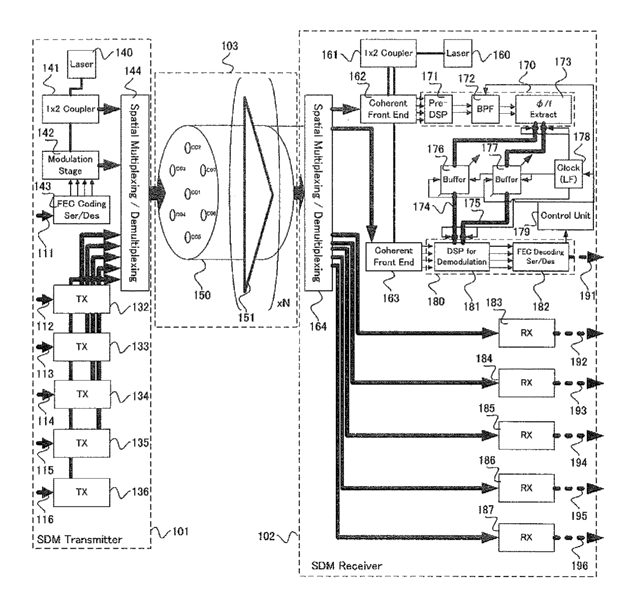
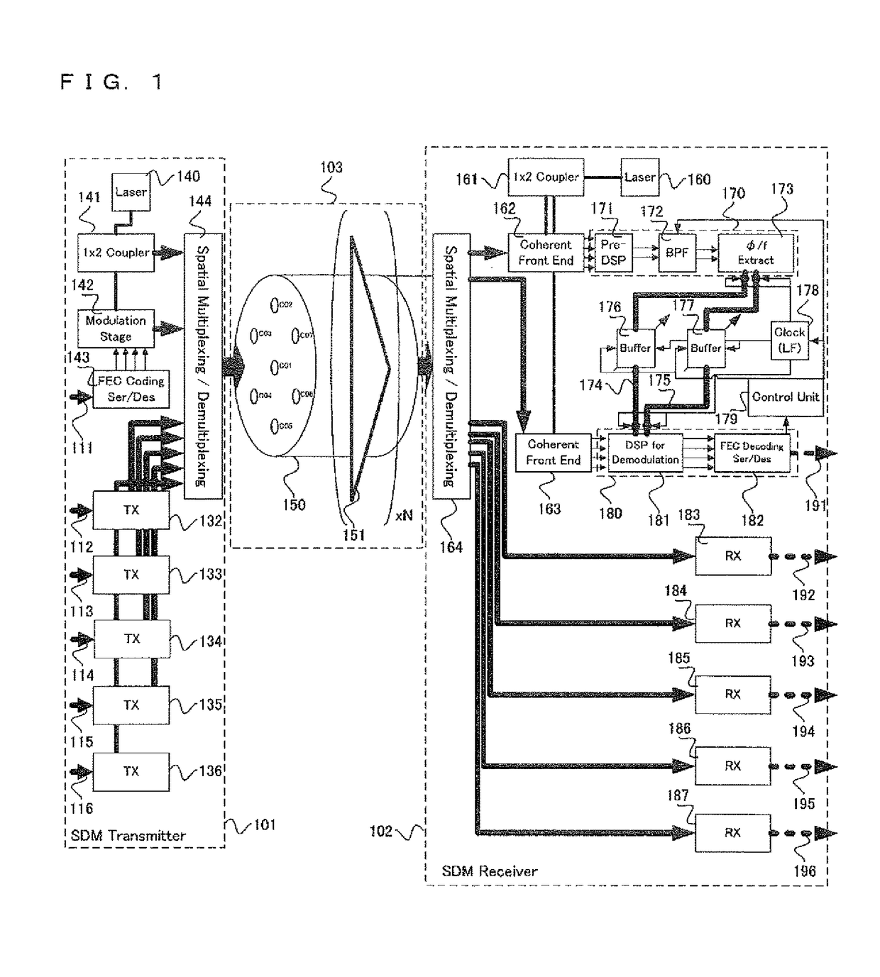
[0054]FIG. 1 is a schematic representation of an optical system including an optical transmitter 101, which uses SDM, an optical receiver 102, which uses SDM and a transmission line 103, which uses MCF. The transmitter 101 and the receiver 102 are communicating through the line 103, which is composed of N spans of multicore fiber, with 7 cores, with multicore amplification at each span. Higher or lower core count can be used, provided that MCF 150, amplifier 151, transmitter 101 and receiver 102 are equipped accordingly to the number of cores.

[0055]The transmitter 101 is fed with 6 binary data lanes denoted with the numerals 111, 112, 113, 114, 115 and 116, which are used to modulate six respective lightwave signals with the respective modulation stage 142, transmitters 132, 133, 134, 135 and 136. The six lightwave signals are spatially multiplexed with the multiplexer 144 and are launched in 6 cores of the MCF, using all cores except one of the multi...


PUM


Abstract

The reception (102) reception unit includes; a first processing unit processing a first signal received from a source channel, and including a filtering unit to filter said first signal in digital domain, and extract unit to extract a information from said first signal; a second processing unit processing a second signal received from a destination channel, and said source channel and said destination channel are distinct each other; a third processing unit providing said information extracted from said first signal to said second signal said third processing unit executes; providing said information from said first processing unit to said second processing unit using information lanes of a clock rate strictly lower than a symbol rate of said second signal, a monitoring unit to generate a monitor signal according to the quality of said second signal; and a control unit controlling a skew between said first signal and said second signal in a bandwidth of said filtering units in said first processing unit.

Description

TECHNICAL FIELD[0001]The present invention relates generally to optical communication technologies and more particularly to optical communication technologies, where the data is transmitted between parallel channels multiplexed spatially inside the fiber.BACKGROUND ART[0002]In order to optimize the investment in optical fiber links, it is desirable to increase the capacity of said links. This can be achieved by increasing the Spectral Efficiency (SE) of the signals transmitted on said links. A common way to achieve is to use more efficient modulation formats for the transmitted information. This can be used in conjunction with Wavelength Division Multiplexing (WDM). Higher capacity systems with line rate in the range of 40 Gb / s or 100 Gb / s utilize modulation scheme based on Quadrature Phase Shift Keying (QPSK), which codes the information on four phase levels. Therefore, two binary bits can be coded per transmitted symbol. In this manner, the necessary bandwidth of the optical spect...

Claims


Application Information

Patent Timeline
Patent Type & Authority Patents(United States)
IPC IPC(8): H04B10/61H04B10/2581H04L25/14H04B10/077H04J14/04H04J14/00
CPCH04B10/615H04B10/6163H04B10/6164H04B10/6165H04J14/00H04J14/04H04L25/14H04B10/0775H04B10/2581H04B10/611H04B10/65
Inventor LE TAILLANDIER DE GABORY, EMMANUELITO, TOSHIHARUARIKAWA, MANABU
Owner NEC CORP
Why Eureka
Try Eureka