Digital off-axis heterodyne holographic interferometry for detecting vibration amplitude

a holographic interferometry and digital technology, applied in the field of digital off-axis heterodyne holographic interferometry for detecting vibration amplitude, can solve problems such as limiting applications, and achieve the effect of not requiring complex electronics and less costly

Active Publication Date: 2017-08-15
CENT NAT DE LA RECHERCHE SCI
View PDF0 Cites 0 Cited by
  • Summary
  • Abstract
  • Description
  • Claims
  • Application Information

AI Technical Summary

Benefits of technology

[0012]the calculation of the time-frequency Fourier transform of the complex amplitudes of said holograms, making it possible to obtain, at each point of the spatial field, a frequency spectrum of the optical beats between the frequency components of the reference wave and of the signal wave, the optical beats spectrum comprising at least two bands at frequencies equal to the frequency offsets δ1 and δ2; and
[0014]The applicant has demonstrated that, by virtue of the method thus described, a significantly improved signal-to-noise ratio of measurements of vibration amplitudes could be obtained, notably by virtue of the simultaneous measurement of the bands of the frequency spectrum of the holograms. Very good results are obtained by working on one of the first modulation bands of the signal wave (q=±1) and with a reference wave exhibiting two components offset in frequency. It is also possible to increase the signal-to-noise ratio by increasing the number of components of the reference wave. By working on modulation bands of higher order, it is also possible to access greater vibration amplitudes.
[0017]According to a variant, the method comprises the emission of a laser wave of frequency ω1, and the separation of the laser emission wave to form the object illumination wave and a second wave sent to an optical frequency shift optoelectronic device to form the reference wave, thus making it possible to form mutually coherent illumination and reference waves.
[0019]According to a variant, in the case of a forced excitation of the object, the excitation frequency is temporally variable in a continuous manner between a lower excitation frequency ωI and an upper excitation frequency ωF for a given time (T), the acquisition and the processing of the interferograms being performed during said time. The variation of the excitation frequency is for example linear between the lower and upper values. This continuous variation of the excitation frequency, simultaneously with a variation of one of the reference wave offset frequencies, allows for a locking of the phase delay of the vibration relative to the excitation, allowing for a more accurate measurement of the phase delay.
[0027]means for calculating the time-frequency Fourier transform of the complex amplitudes of said holograms, making it possible to obtain, at each point of the spatial field, a frequency spectrum of the optical beats between the frequency components of the reference wave and of the signal wave, the optical beats spectrum comprising at least two bands at frequencies equal to the frequency offsets δ1 and δ2; and
[0032]Alternatively, the optical frequency shift optoelectronic device comprises a Pockels cell. The Pockels cell offers the advantage of being less costly than acousto-optical modulators and of not requiring complex electronics.

Problems solved by technology

However, in conventional holography, the quantitative information recorded (amplitude and phase of the signal wave) is not directly accessible, which limits the applications thereof.

Method used


Image

  • Digital off-axis heterodyne holographic interferometry for detecting vibration amplitude
  • Digital off-axis heterodyne holographic interferometry for detecting vibration amplitude
  • Digital off-axis heterodyne holographic interferometry for detecting vibration amplitude

Examples


Embodiment Construction

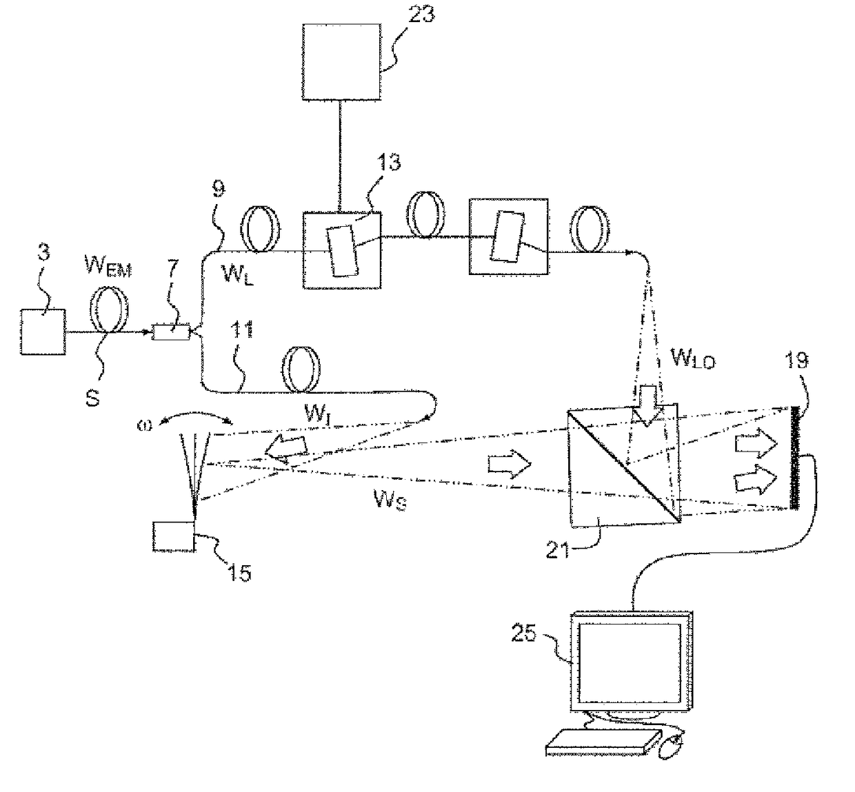
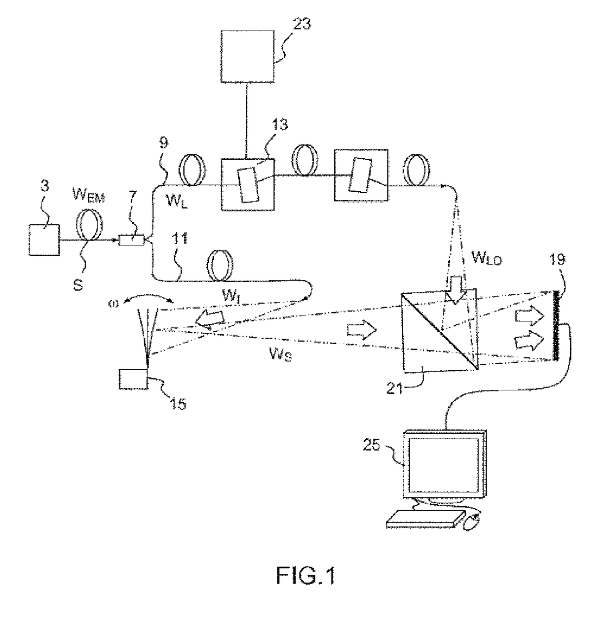
[0044]FIG. 1 illustrates a diagram of an exemplary digital holography device according to the invention. In this example, the device is fibered. The device makes it possible to record and process interferograms of an object exhibiting at least one vibration frequency w, in order to determine the amplitude and / or the phase of vibration thereof. Hereinafter in the application, the term “vibration frequency”ω will simply be used to express the angular frequency for pulsation). The vibration phase is more specifically defined, in the case of an object subjected to a forced sinusoidal excitation, by the phase delay relative to the excitation phase. The capacity to measure vibration amplitudes of very low amplitudes of an object and the phase of the vibration of the object subjected to a forced vibration can make it possible to give very fine information on the nature of the object, such as its mechanical integrity, its quality and, if appropriate, its damage state. For this, the device a...


PUM

PropertyMeasurementUnit
frequencyaaaaaaaaaa
frequencyaaaaaaaaaa
frequenciesaaaaaaaaaa

Abstract

The invention relates to a digital holography method for detecting the vibration amplitude of an object (15) having a vibration frequency ω, comprising: generating object illumination waves (Wt) and reference waves (WLO); acquiring interferograms between the reference wave (WLO) and a signal wave (Ws) by means of a bandwidth ω s detector (19), the reference wave comprising two components ELO1, ELO1 of frequencies ω1, ω2 that are respectively staggered in relation to the laser frequency ωL by a quantity δ1=γ1ωs and δ2=qω+γ2ωs, where q is an integer and −0.5≦γ1, γ2≦0.5; and calculating the vibration amplitude of the object from the optical beats spectrum deduced from the complex amplitude of an interferogram.

Description

TECHNICAL FIELD OF THE INVENTION[0001]The present invention relates to a digital off-axis heterodyne holographic interferometry device and method, in particular for measuring mechanical vibrations of nanometric amplitudes.PRIOR ART[0002]Holography is a method which makes it possible to reconstruct an image in three dimensions (3D) of an object from the recording of an interference figure between two coherent waves, a reference wave and a wave diffused by the object to be observed. In the case of conventional holographic interferometry, the recording is performed on a photographic plate. Once the plate is developed by known photography methods, a hologram is obtained. The 3D image is reconstructed by illuminating the hologram with the reference wave which then produces a wave directly transmitted (order 0) and two diffracted light waves, an object wave (or signal wave) which reconstitutes a virtual image of the object and a conjugate wave which forms a parasitic real image which hamp...

Claims


Application Information

Patent Timeline
Patent Type & Authority Patents(United States)
IPC IPC(8): G01B9/02G03H1/08G03H1/00G01B9/021G01N21/45G03H1/04
CPCG01B9/021G01N21/453G03H1/0005G03H1/0443G03H1/0866G03H2001/0033G03H2001/0456G03H2001/0463G03H2210/62G03H2227/03
Inventor ATLAN, MICHAELSAMSON, BENJAMIN
Owner CENT NAT DE LA RECHERCHE SCI
Why Eureka
Try Eureka