Eureka AIR delivers breakthrough ideas for toughest innovation challenges, trusted by R&D personnel around the world.

Graphene serving as cathode of X-ray tube and X-ray tube thereof

a technology of x-ray tube and graphene, which is applied in the direction of x-ray tube electrodes, electrical devices, electric discharge tubes, etc., can solve the problems of low conversion efficiency from electric energy to x-rays, low efficiency of x-ray tube, etc., to achieve short service life, low conversion efficiency, and poor stability

Active Publication Date: 2017-08-15
CHONGQING XINHE QIYUE TECH CO LTD
View PDF7 Cites 2 Cited by
  • Summary
  • Abstract
  • Description
  • Claims
  • Application Information

AI Technical Summary

Benefits of technology

The patent is describing a new type of X-ray tube that has several technical advantages. It is highly efficient, meaning it can produce X-rays with less stray radiation. It is also easy to focus and can operate for a long time under a high voltage. The tube has good stability and can be controlled to produce a specific size of X-ray beam with specific electron flows. Additionally, the tube can control the number of X-ray emissions by regulating the voltage, ensuring precise control of the tube current. Overall, this new tube offers improved safety, reduced radiation dosage, and enhanced control for various applications such as medical treatment and industrial inspection.

Problems solved by technology

However, such an X-ray tube is high in energy consumption and low in efficiency, and the conversion efficiency from electric energy to X-rays is less than 1%.
Field emission X-ray tubes all adopt carbon nano-tubes (CNTs) as cathodes (electron emission sources), and the CNTs have the following drawbacks due to growth techniques and structural limitation thereof, e.g., an insecure bonding between carbon tubes and bases, an insufficient voltage endurance capability with a highest voltage no more than 100 KV; the structure of the carbon tube is vulnerable when operating under a high voltage and tends to become incapable of emitting, meanwhile the vacuum degree within the tube is reduced, which makes damage to the ray tubes and shortens the service life; and poor uniformity in the direction of electron emission as a result of the disordered growth of the carbon tubes.

Method used


Image

  • Graphene serving as cathode of X-ray tube and X-ray tube thereof
  • Graphene serving as cathode of X-ray tube and X-ray tube thereof
  • Graphene serving as cathode of X-ray tube and X-ray tube thereof

Examples


Embodiment Construction

[0022]A high-efficiency graphene cathode field emission X-ray tube of the present disclosure will be further detailed with reference to attached drawings in conjunction with particular assembly processes and working principles.

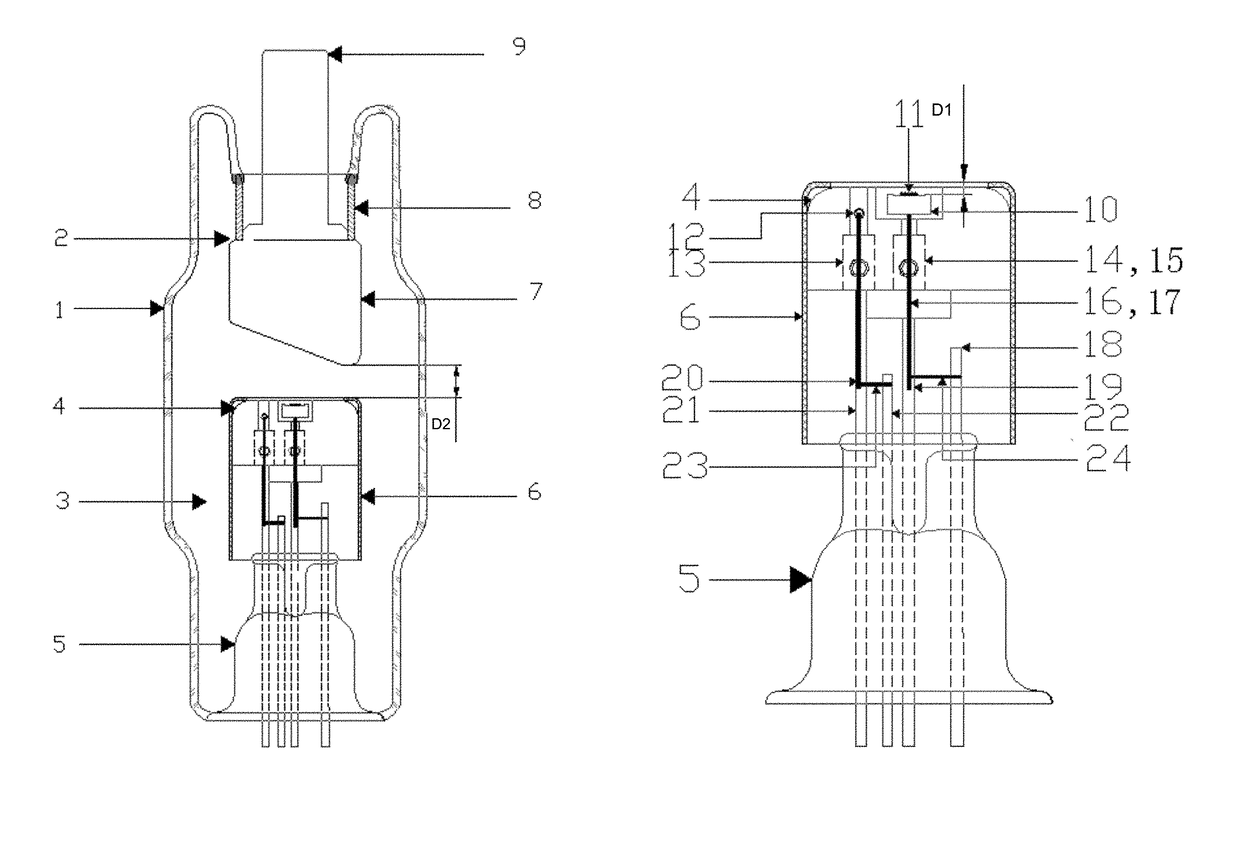
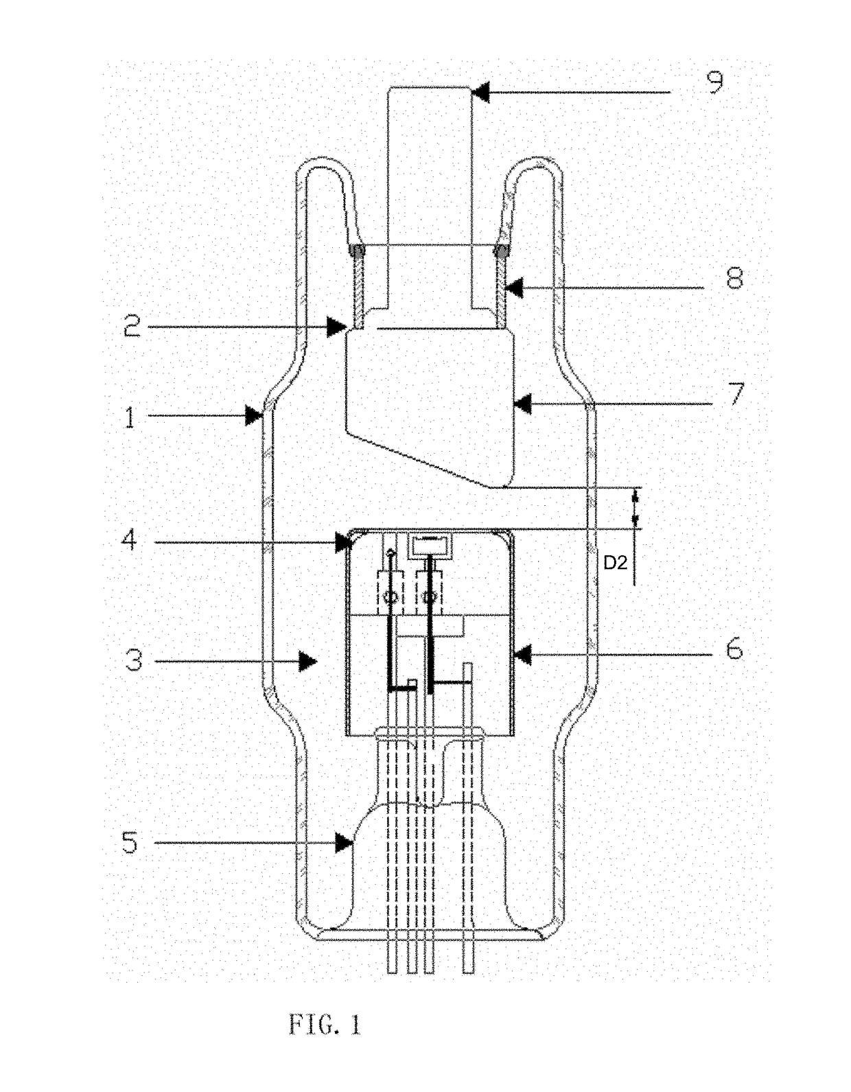
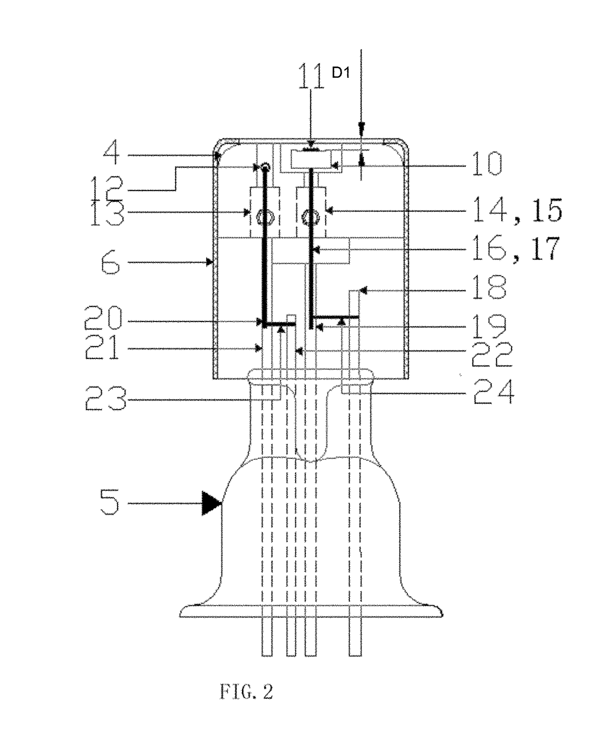
[0023]Taking advantage of good field emission performance of a graphene cathode, the high-efficiency graphene cathode field emission X-ray tube of the present disclosure has the graphene cathode fixed in a cathode assembly as an electron emission source and then encapsulates the cathode assembly together with an anode assembly into a vacuum glass tube 1. A high voltage is applied between an anode and a cathode so that the graphene cathode emits electrons, and the emitted electrons, under the focusing effect of a cathode shield and the high voltage at the anode, bombard an anode target at a high speed along a certain direction to generate X-rays. The emission threshold of the graphene cathode is less than 0.40 V / μm, and the highest withstand voltage is larger t...


PUM


Abstract

Graphene serving as the cathode of an X-ray tube, and a high-efficiency graphene cathode field emission X-ray tube. The graphene cathode field emission X-ray tube is high in conversion efficiency and less in stray radiation, reduces radiation dosage acting upon human body when used in the fields of medical treatment, security inspection and the like; the graphene cathode field emission X-ray tube is easy to realize a micro-focus X-ray tube, strong in emissive power and high in voltage resistance, and can be applied to the fields of semiconductor detection, industrial flaw detection and the like; in addition, the graphene cathode field emission X-ray tube is good in controllability, free from cathode heating. The graphene cathode field emission X-ray tube also has the characteristics of good stability and long service life.

Description

CROSS REFERENCE TO RELATED APPLICATIONS[0001]The present application is a 35 U.S.C. §371 National Phase conversion of International (PCT) Patent Application No. PCT / CN2014 / 072019, filed on Feb. 13, 2014, which claims the benefit of Chinese Patent Application No. 201310166516.9, filed on May 8, 2013, the disclosure of which is incorporated by reference herein. The PCT International Patent Application was filed and published in Chinese.FIELD[0002]The present disclosure relates to graphene serving as a cathode of an X-ray tube, and more particularly, to graphene serving as a high-efficiency graphene cathode field emission X-ray tube.BACKGROUND[0003]X-ray tubes are apparatuses mainly used in the medial field for medical diagnosis and treatment, and used in the industrial field for nondestructive testing, structural analysis, spectrum analysis, film exposure, etc., of materials. X-rays are harmful to human body, so effective protective measures are necessary during the use of X-rays.[000...

Claims


Application Information

Patent Timeline
IPC IPC(8): H01J35/06H01J35/08
CPCH01J35/065H01J35/06H01J35/08
Inventor LI, KUI-YANG
Owner CHONGQING XINHE QIYUE TECH CO LTD
Why Eureka
Eureka Blog
Learn More