
Nanoparticle-coated multilayer shell microstructures

Active Publication Date: 2017-08-22
HRL LAB
View PDF18 Cites 31 Cited by
  • Summary
  • Abstract
  • Description
  • Claims
  • Application Information

AI Technical Summary

Benefits of technology

The present invention provides a material with hollow microstructures that have multiple shells, including an inner shell and an outmost shell, with a combined thickness that is less than one-tenth of the shortest diameter. The microstructures may contain nanoparticles with an oxide layer and may be dispersed in a matrix material. The hollow microstructures may be used as thermal insulation or thermal barrier coatings on metallic or ceramic substrates. The technical effects of the invention include improved thermal insulation and reduced thickness of the microstructures.

Problems solved by technology

For such an application, low thermal conductivity and low heat capacity is required.
Both types of cellular architecture are not favorable to structural integrity, and the brittle ceramic material causes low damage tolerance.
Another disadvantage is that both cellular architectures are fairly open and gases from the outside can access many of the pores and even the underlying substrate.
Shuttle tiles exhibit low thermal conductivity and low heat capacity, but these materials are designed for extreme temperatures (greater than 1200° C.) and have poor mechanical properties such as low crush strength.
These tiles are open cellular structures and absorb significant amount of water because of open porosity, which increases mass and can result in damage when the water is vaporized during exposure to high temperatures.

Method used


Image

  • Nanoparticle-coated multilayer shell microstructures
  • Nanoparticle-coated multilayer shell microstructures
  • Nanoparticle-coated multilayer shell microstructures

Examples


Embodiment Construction

[0048]The structures, compositions, and methods of the present invention will be described in detail by reference to various non-limiting embodiments.

[0049]This description will enable one skilled in the art to make and use the invention, and it describes several embodiments, adaptations, variations, alternatives, and uses of the invention. These and other embodiments, features, and advantages of the present invention will become more apparent to those skilled in the art when taken with reference to the following detailed description of the invention in conjunction with the accompanying drawings.

[0050]As used in this specification and the appended claims, the singular forms “a,”“an,” and “the” include plural referents unless the context clearly indicates otherwise. Unless defined otherwise, all technical and scientific terms used herein have the same meaning as is commonly understood by one of ordinary skill in the art to which this invention belongs.

[0051]Unless otherwise indicated...


PUM

PropertyMeasurementUnit
Thicknessaaaaaaaaaa
Thicknessaaaaaaaaaa
Thicknessaaaaaaaaaa

Abstract

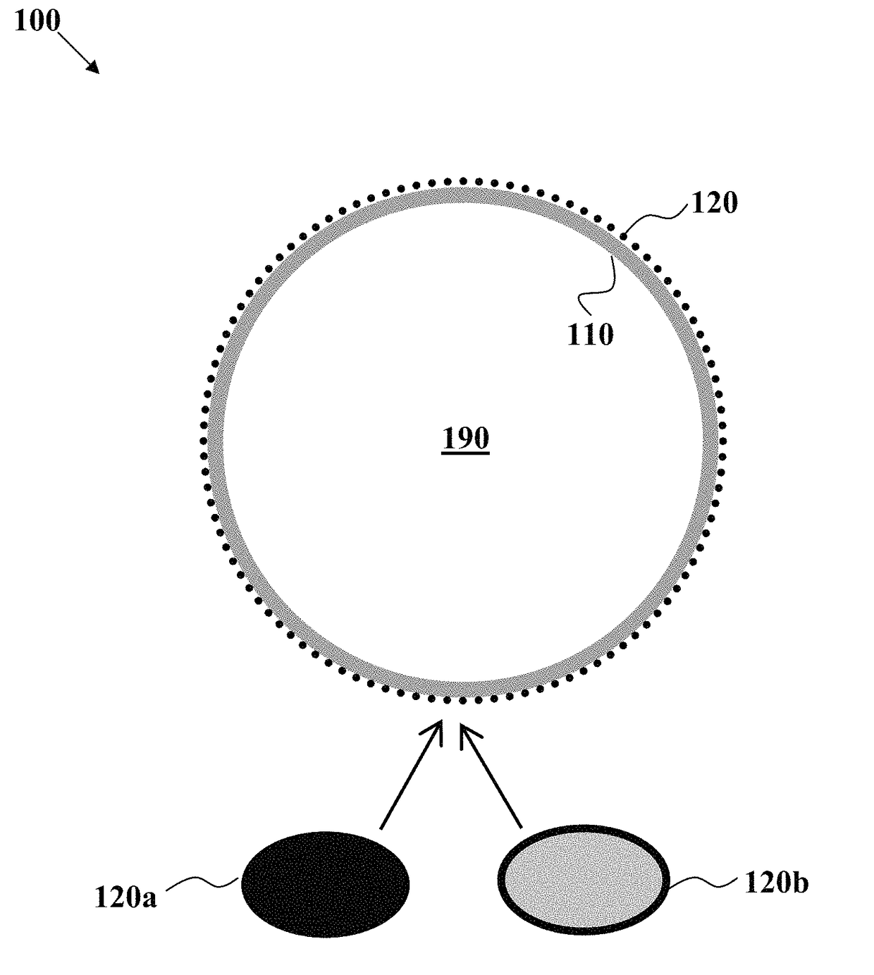
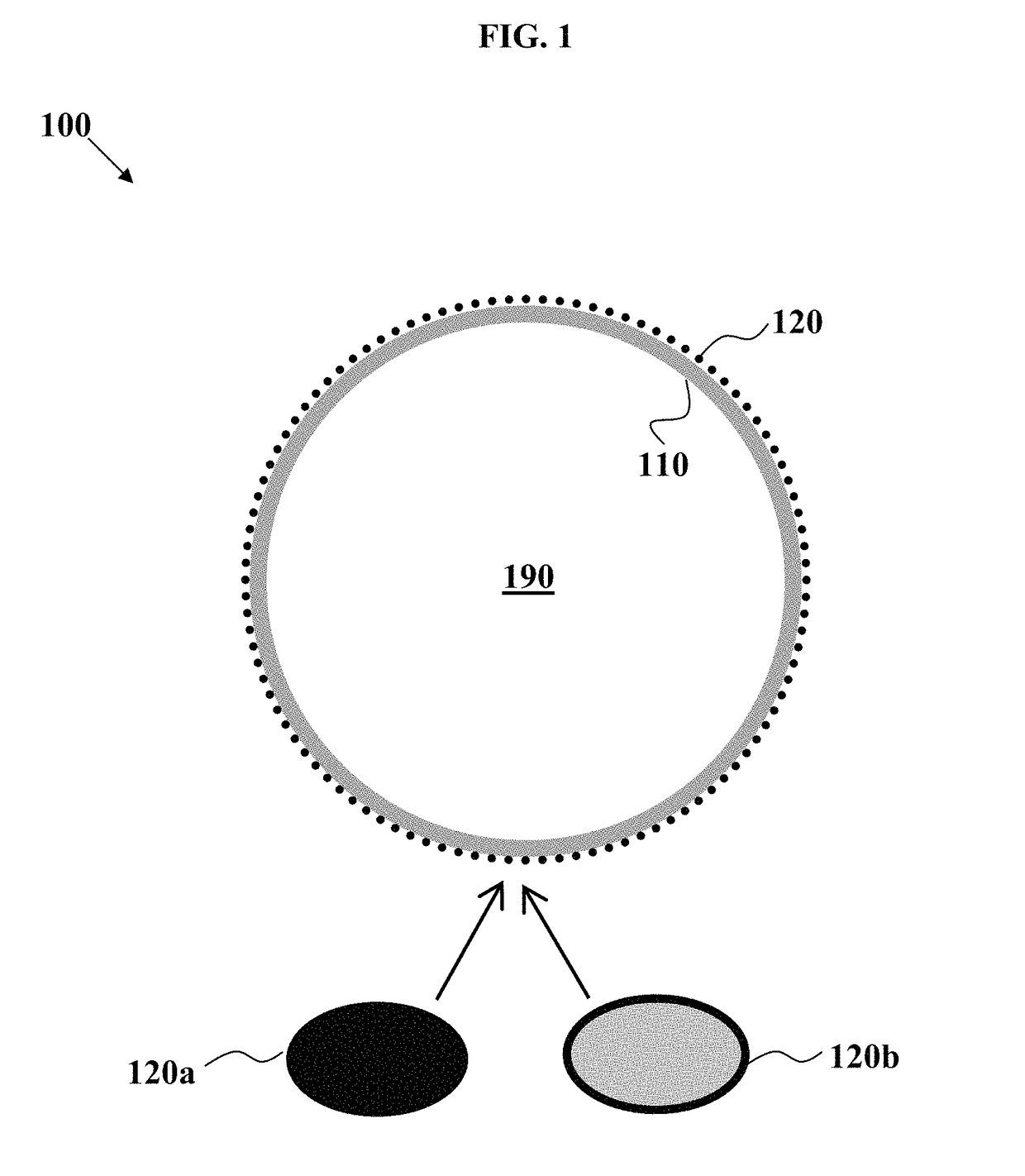
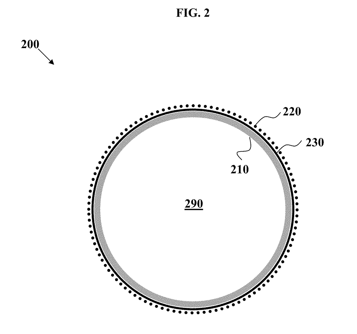
Novel nanoparticle-coated multilayer shell microstructures are disclosed herein. Some variations of the invention provide a material comprising a plurality of hollow microstructures characterized by an average shortest diameter from about 5 microns to about 1 millimeter, wherein each of the microstructures comprises multiple shells, including at least an inner shell and an outmost shell, with a combined thickness that is less than one-tenth of the average shortest diameter. The inner shell and the outmost shell have different composition. The outmost shell comprises nanoparticles sized between about 10 nanometers to about 500 nanometers, and the nanoparticles each contain an oxide and / or are surrounded by an oxide layer having a layer thickness of at least 1 nanometer. Several microstructure configurations are illustrated in the drawings.

Description

PRIORITY DATA[0001]This patent application is a non-provisional application with priority to U.S. Provisional Patent App. No. 62 / 002,915, filed May 26, 2014, which is hereby incorporated by reference herein.FIELD OF THE INVENTION[0002]The present invention generally relates to microstructures coated with nanoparticles.BACKGROUND OF THE INVENTION[0003]Metal alloy coatings improve chemical and physical damage resistance as well as structural rigidity on microparticles and on solids made from microparticles. Metal alloy-coated microparticles are of interest for acoustic metamaterials, filler materials (for weight reduction), structural lightweight materials, corrosion-resistant coatings, energy-absorption materials, thermal insulation materials, and thermal barrier coatings.[0004]Thermal barrier coatings are highly advanced material systems usually applied to metallic surfaces, such as gas turbines or aero-engine parts, operating at elevated temperatures, as a form of exhaust heat mana...

Claims


Application Information

Patent Timeline
IPC IPC(8): B32B5/16C08K3/08C09D1/00C23C12/00C23C24/10C23C24/08C23C30/00B22F1/00B22F1/02B22F1/0655B22F1/102B22F1/16B22F1/17B22F1/18C09D7/61
CPCC09D1/00C08K3/08C23C24/085C23C12/00B22F1/025B22F1/02C23C30/00B22F1/0051C23C24/103C08K2003/0812C08K2003/0862C01P2004/34C01P2004/60Y10T428/2991C01P2004/61C01B33/113B22F2998/10B22F2999/00C01B32/00C09D7/61C23C18/1635C25D7/00C08K9/12B22F1/0655B22F1/17B22F1/16B22F1/18B22F1/102C22C1/0433B22F2009/045B22F3/1112B22F3/10B22F3/12C22C1/08B22F1/054B22F1/056Y02T50/60
Inventor GROSS, ADAM F.NOWAK, ANDREW P.SCHAEDLER, TOBIAS A.MARTIN, JOHN H.
Owner HRL LAB
Learn More