Electro-optic optical modulator devices and method of fabrication

a technology of optical modulator and electrode, applied in the direction of optical waveguide light guide, optical light guide, instrument, etc., can solve the problems of low electro-optical efficiency of conventional optical modulator waveguide, large footprint unnecessarily large cost of conventional optical modulator, etc., and achieve the effect of reducing the size of electro-optic modulator

Active Publication Date: 2017-08-29
PARTOW TECH LLC
View PDF2 Cites 32 Cited by
  • Summary
  • Abstract
  • Description
  • Claims
  • Application Information

AI Technical Summary

Benefits of technology

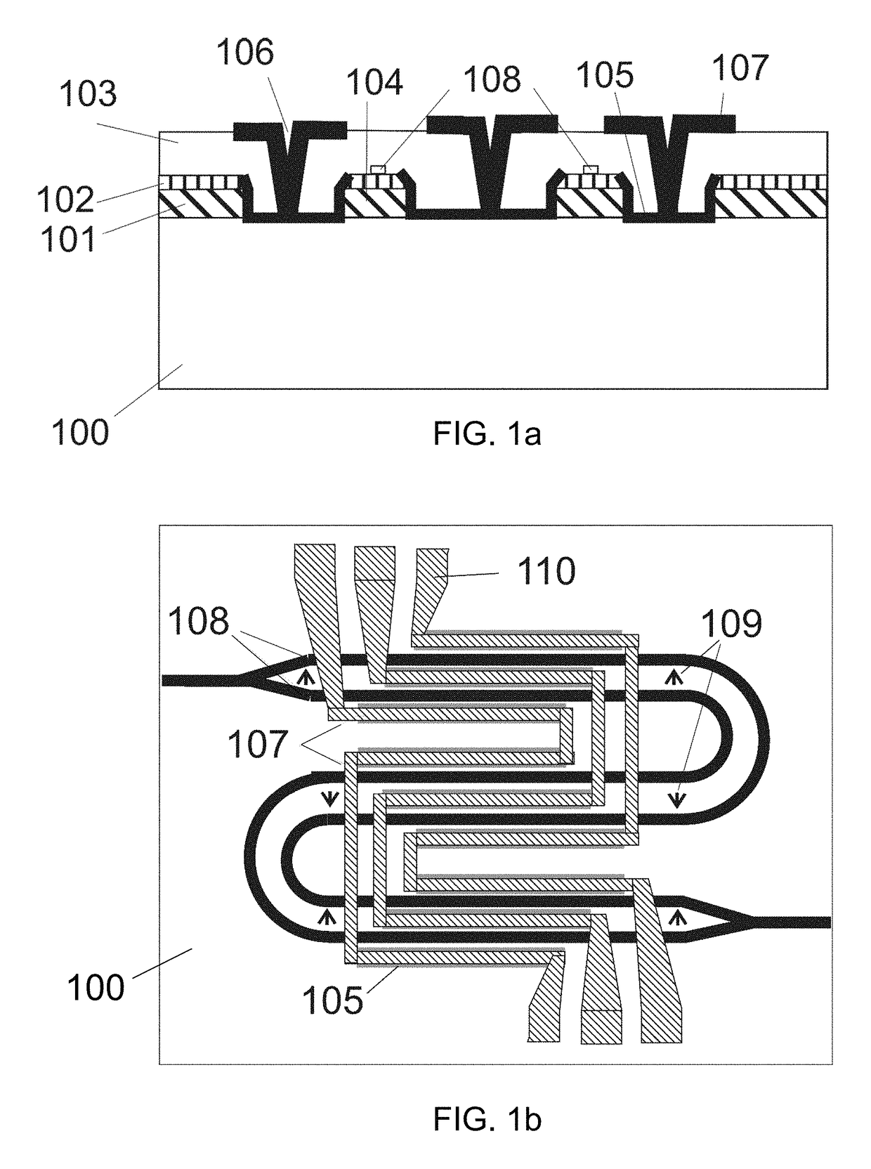
[0009]In addition, an embodiment of the invention also discloses a novel layout for an optical modulator, wherein the novel layout incorporates foldable modulation arms in the optical modulator and poling ...

Problems solved by technology

This conventional design is vulnerable to interference in the second coupler, thus resulting in an intensity modulation.
Conventional optical modulator waveguides have low electro-optical eff...

Method used


Image

  • Electro-optic optical modulator devices and method of fabrication
  • Electro-optic optical modulator devices and method of fabrication
  • Electro-optic optical modulator devices and method of fabrication

Examples


Embodiment Construction

[0026]Specific embodiments of the invention will now be described in detail with reference to the accompanying figures. Like elements in the various figures are denoted by like reference numerals for consistency.

[0027]In the following detailed description of embodiments of the invention, numerous specific details are set forth in order to provide a more thorough understanding of the invention. However, it will be apparent to one of ordinary skill in the art that the invention may be practiced without these specific details. In other instances, well-known features have not been described in detail to avoid unnecessarily complicating the description.

[0028]The detailed description is presented largely in terms of procedures, logic blocks, processing, and / or other symbolic representations that directly or indirectly resemble one or more optical modulator production methods and spatially-compact optical modulators that exhibit a low DC bias drift and a high modulation speed, in accordanc...


PUM


Abstract

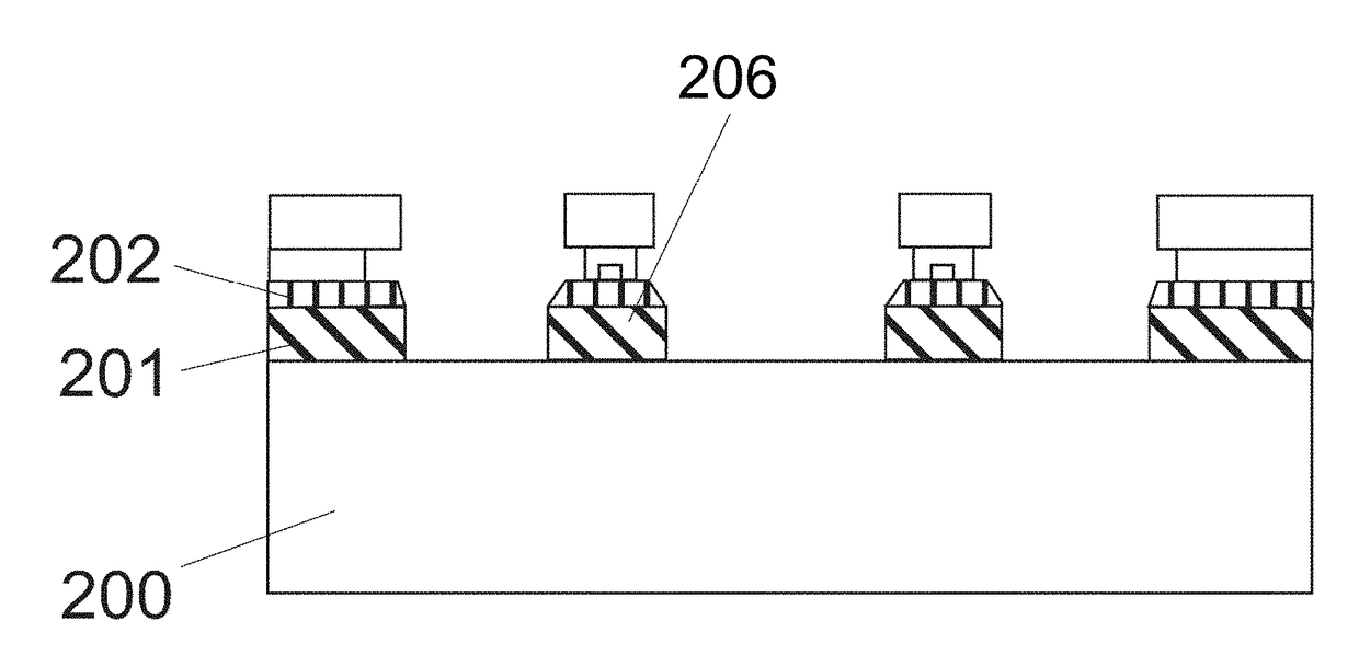
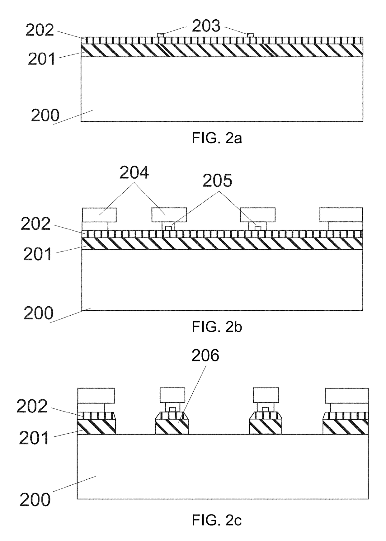
A novel electro-optic optical modulator device and a related method for creating the novel optical modulator device are disclosed. In one embodiment, the novel optical modulator comprises a high index contrast optical waveguide, a mesa region, electrical modulation electrodes, RF transmission lines, and interconnection layers. The high index contrast optical waveguide comprises an electro-optic slab core region and a high index ridge core region. A mesa section which includes the core regions can be formed, and electrical modulation electrodes are placed on etched sidewalls of the mesa section to achieve electro-optical index modulation of the electro-optic slab core region. The RF transmission lines include RF electrodes that connected to the electrical modulation electrodes. The interconnection layers connect the modulation electrodes with the RF electrodes by using etched vias. The novel optical modulator can also incorporate foldable modulation arms for poling in the electro-optic slab core region.

Description

FIELD OF THE INVENTION[0001]The present invention generally relates to a method for producing compact electro-optical modulators and other integrated electro-optical elements. The present invention also relates to electro-optical modulators that are based on thin film lithium niobate or lithium tantalite waveguides, and a mesa that is etched into these materials and radio frequency (RF) transmission lines. The present invention also relates to optical modulator devices that are fabricated on silicon substrates Furthermore, the present invention also relates to low direct current (DC) drift modulators and high speed modulators. In addition, the present invention also relates to compact modulators with poled and folded arms that accommodate fabrication of small footprint devices made from electro-optical materials. Furthermore the invention relators to resonance enhanced Mach-Zehnder modulators made using electro-optic materials.BACKGROUND OF THE INVENTION[0002]In a variety of electro...

Claims


Application Information

Patent Timeline
IPC IPC(8): G02F1/225G02B6/132G02B6/136G02B6/12G02B6/122G02F1/21
CPCG02F1/2255G02B6/132G02B6/136G02B6/12009G02B6/1225G02F2001/212G02B2006/12173G02B2006/12061G02F2202/07G02B6/122G02B6/1223G02B2006/1204G02B2006/12045G02B2006/12142G02F1/212
Inventor RABIEI, PAYAM
Owner PARTOW TECH LLC
Why Eureka
Try Eureka