Steam power plant with a ground heat exchanger

a ground heat exchanger and steam power technology, applied in steam/vapor condensers, sustainable buildings, lighting and heating apparatus, etc., can solve the problems of large water loss, unsuitability, and many sunny regions affected by water shortage, and achieve relatively high outer temperatures, reduce the degree of efficiency, and high solar radiation intensity

Inactive Publication Date: 2017-09-26
GENERAL ELECTRIC TECH GMBH
View PDF16 Cites 0 Cited by
  • Summary
  • Abstract
  • Description
  • Claims
  • Application Information

AI Technical Summary

Benefits of technology

[0021]The concept of coupling a ground heat exchanger according to the invention with a collector field is especially effective, as solar collectors are built in areas and regions with high solar radiation intensi...

Problems solved by technology

Basically, many sunny regions are affected by water shortage.
1. The fresh water cooling uses cooling water from surface water, which can be redirected after the cooling-process.
2. With the cooling in wet-cooling tower the greatest cooling effect does not occur due to the surrounding air, but due to the evaporation process. Wherein, however, great water quantities are lost, for which reason this variation is not suited for regions with water shortage.
3. With the direct ...

Method used


Image

  • Steam power plant with a ground heat exchanger
  • Steam power plant with a ground heat exchanger
  • Steam power plant with a ground heat exchanger

Examples


Embodiment Construction

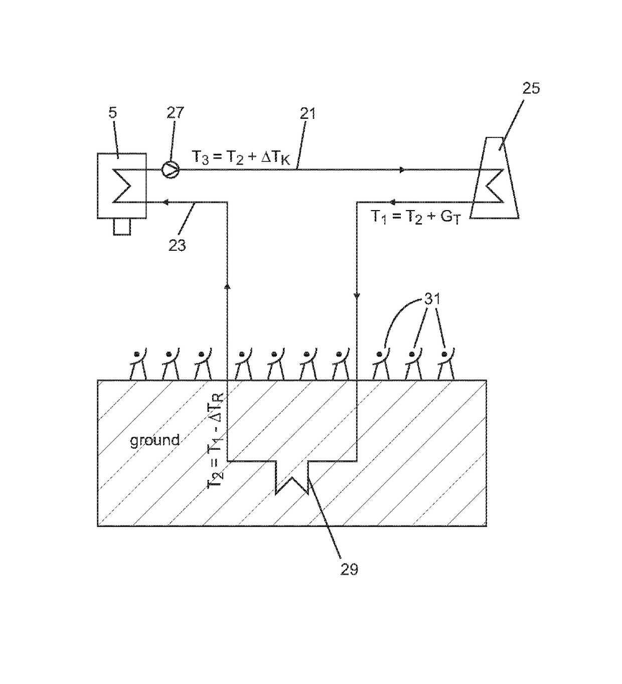
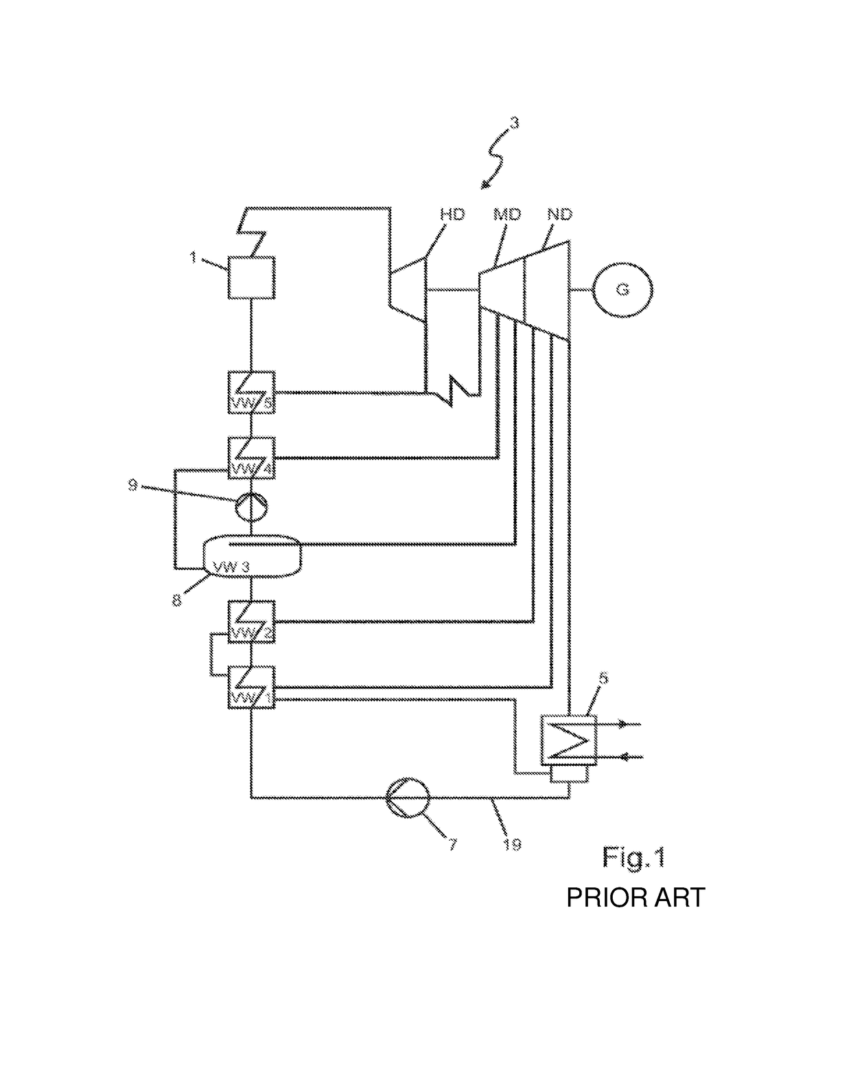
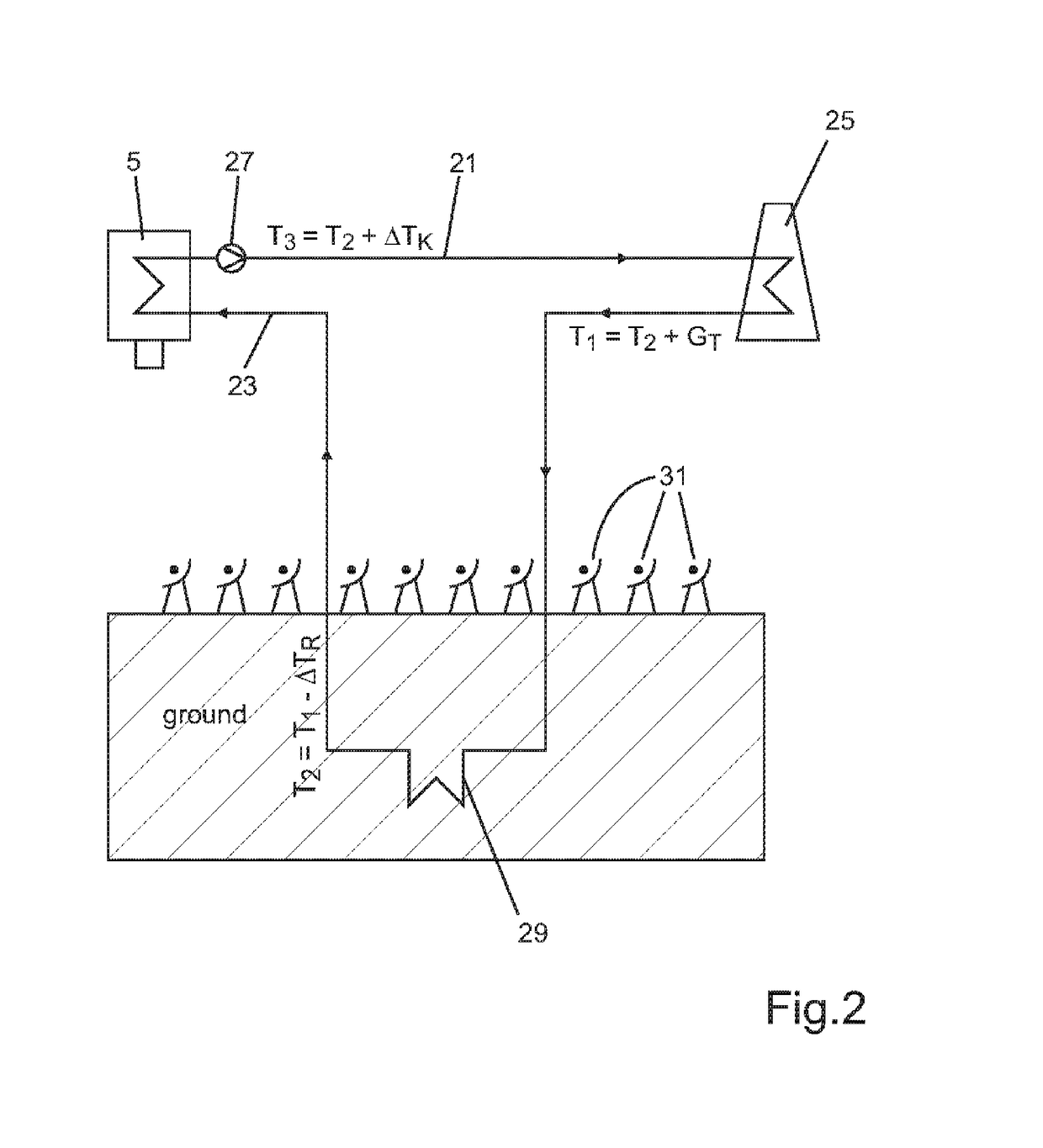
[0030]In FIG. 1 a steam power plant is represented as block diagram. The steam power plant can be designed as conventional steam power plant fuelled with fossils or with biomass. Alternatively the steam power plant can be designed as solar-thermal steam power plant where the energy supplied to the water-steam-cycle is generated in a collector field (cf. FIG. 2) out of solar radiation. The invention can also be used for hybrid forms, where the required energy is provided by combustion of fossil and / or organic fuels and, if available, by solar collectors.

[0031]FIG. 1 essentially serves for designating the individual components of the power plant and representing the overall context of the water-steam-cycle, as for clarity-reasons in the following figures only the parts of the water-steam-cycle essential to the invention are represented.

[0032]In a steam generator 1 utilizing fossil fuels or biomass out of the feed water live steam is generated, which is expanded in a steam turbine 3 an...


PUM


Abstract

A Steam power plant comprising a steam turbine (3) and a condenser (5), wherein the condenser (5) is disclosed, comprising a first heat sink being a ground heat exchanger (29) is connected to the condenser during times when ground temperature is lower than air temperature; and a second heat sink being an above-ground heat exchanger is connected to the condenser during times when ground temperature is not lower than air temperature.

Description

CROSS-REFERENCE TO RELATED APPLICATION[0001]This is a U.S. national stage of application No. PCT / EP2011 / 067178, filed on Sep. 30, 2011. Priority under 35 U.S.C. §119(a) and 35 U.S.C. §365(b) is claimed from European Patent Application No. 10012540.0, filed on Sep. 30, 2010, incorporated herein in its entirety by reference.BACKGROUND[0002]Due to the increasing world population, the increasing energy demand and due to the international discussion concerning climate warming governments in various regions enforce the exploitation of regenerative energies. Before this background solar-thermal power plants in sunny regions in future are attributed a considerable share of the energy mix. Basically, many sunny regions are affected by water shortage. Thus it must be taken as a basis that solar-thermal power plants are often carried out with dry cooling and will thus directly be dependent on the surrounding temperature.[0003]Generally in the thermal power plant-technique a difference is made ...

Claims


Application Information

Patent Timeline
IPC IPC(8): F01K9/00F03G6/06F01K7/38F01K7/40
CPCF03G6/06F01K7/38F01K7/40F01K9/00F01K9/003Y02B10/20Y02E10/46F03G6/061
Inventor SCHULE, VOLKERVELM, SILVIA
Owner GENERAL ELECTRIC TECH GMBH
Why Eureka
Try Eureka