Latchable valve and method for operation of the latchable valve

a latchable valve and latching technology, applied in the direction of valve operating means/release devices, machines/engines, etc., can solve the problems of inability to purge fuel vapor canisters, indeterminate valve position information, and large amount of battery power, so as to reduce the power consumption and the cost of valves, prevent run time losses, and reduce the possibility of purging fuel vapor canisters.

Inactive Publication Date: 2017-10-03
FORD GLOBAL TECH LLC
View PDF71 Cites 3 Cited by
  • Summary
  • Abstract
  • Description
  • Claims
  • Application Information

AI Technical Summary

Benefits of technology

[0004]In vehicles such as hybrid-electric vehicles (HEVs) and other vehicles configured to operate for periods without combusting fuel, opportunities to purge the fuel vapor canister may be limited. In order to prevent run time losses from saturating the fuel vapor canister, a fuel tank isolation valve (FTIV) may be coupled between the fuel tank and the fuel vapor canister. By keeping the FTIV closed, fuel vapor remains trapped within the fuel tank. The FTIV may be opened to vent the fuel tank, and to allow refueling vapors to be flowed to the fuel vapor canister. As such, the FTIV may be closed during most periods of engine operation. However, FTIV's, among other solenoid valves, use a considerable amount of battery power to remain energized. Therefore, hatchable valves may be used to reduce the power consumption as well as the cost of the valve.

Problems solved by technology

In vehicles such as hybrid-electric vehicles (HEVs) and other vehicles configured to operate for periods without combusting fuel, opportunities to purge the fuel vapor canister may be limited.
However, FTIV's, among other solenoid valves, use a considerable amount of battery power to remain energized.
However, the valve position information may become invalid or indeterminate for a number of reasons such as tow battery, reflashing of the controller, memory corruption in the controller, and valve replacement.
Invalid valve position information leaves the emission control system in an undesirable state which may lead to increased emissions.
This may take a considerable amount of time, and / or place the valve in a non-optimal position.
In other examples, a dedicated position sensor may be coupled to the valve, though this may increase the cost and complexity of the valve, may require additional solenoid wiring, and may further require additional OBD testing to monitor the function of the position sensor.

Method used


Image

  • Latchable valve and method for operation of the latchable valve
  • Latchable valve and method for operation of the latchable valve
  • Latchable valve and method for operation of the latchable valve

Examples


Embodiment Construction

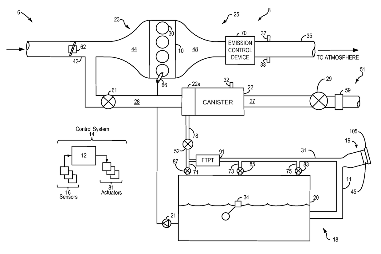
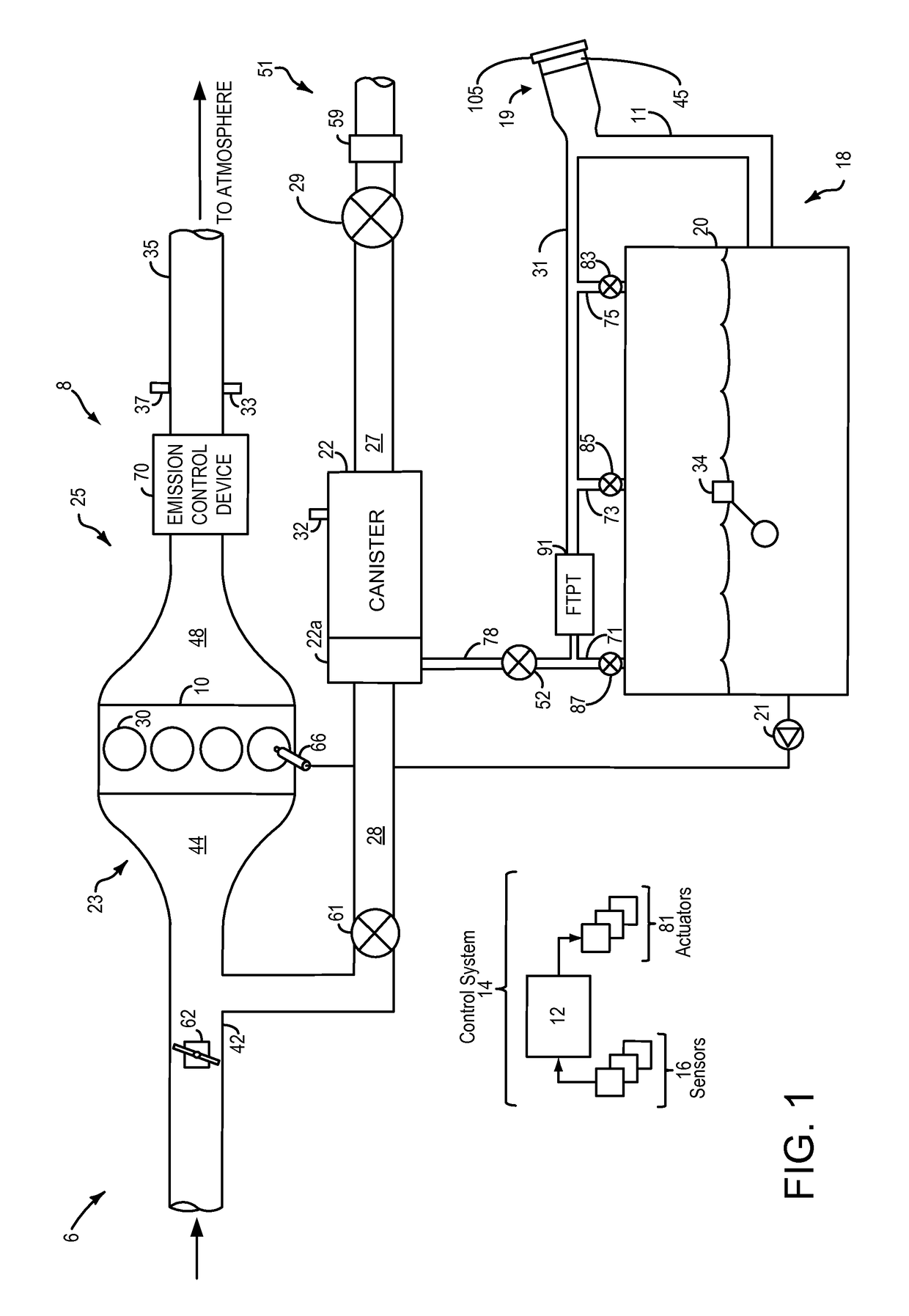
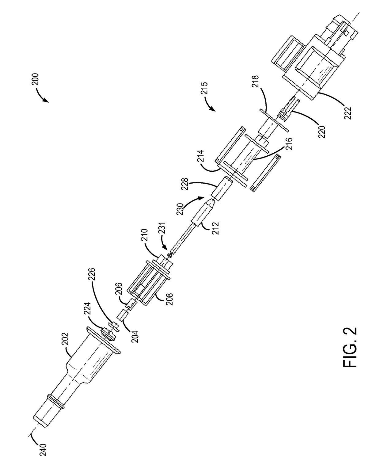
[0018]This description relates to systems and methods for a latchable solenoid valve. In particular, the description relates to systems and methods for determining a position of a latchable solenoid valve. The latchable solenoid valve may be included in a fuel system for a vehicle, the fuel system coupled to an evaporative emissions system as shown schematically in FIG. 1. For example, the latchable solenoid valve may be deployed as a fuel tank isolation valve, coupled between a fuel tank and a fuel vapor canister and configured to regulate the flow of fuel vapor between the fuel tank and the fuel vapor canister. The position of the valve may be adjusted by applying a voltage to a solenoid coil, thus generating a magnetic field which actuates a valve shaft at least partially surrounded by the solenoid coil. For a latchable valve, such as the valve shown in FIG. 2, the valve shaft may latch into place in one or more positions, thus allowing the valve position to be maintained in a po...


PUM


Abstract

A fuel system is provided, including a fuel tank isolation valve comprising an actuation coil and a latchable valve shaft at least partially disposed within the actuation coil. A controller may be configured to indicate a position of the valve shaft based on a measured current-voltage relationship between the first and second terminal wires during a condition in which the magnetic field generated by actuation coil current has a flux density below a threshold required to adjust a position of the latchable valve shaft. In this way, the position of the latchable valve shaft may be indicated without moving the valve shaft, and without requiring a dedicated valve position sensor.

Description

CROSS REFERENCE TO RELATED APPLICATIONS[0001]The present application claims priority to U.S. Provisional Patent Application No. 62 / 111,038, “LATCHABLE VALVE AND METHOD FOR OPERATION OF THE LATCHABLE VALVE,” filed on Feb. 2, 2015, the entire contents of which are hereby incorporated by reference for all purposes.FIELD[0002]The present disclosure relates to an emission control system having a latchable valve and method for determining the valve configuration based on a voltage output of a circuit in the valve.BACKGROUND AND SUMMARY[0003]Vehicles having internal combustion engines employ fuel delivery systems with fuel tanks. Emission control systems may be provided in these vehicles to absorb fuel vapors generated during refueling events, during diurnal cycles, and during vehicle run time. An emission control system may include a fuel vapor canister coupled to the fuel tank configured to store fuel vapor in an adsorbent bed. The adsorbed fuel vapor may then be purged to an engine inta...

Claims


Application Information

Patent Timeline
Patent Type & Authority Patents(United States)
IPC IPC(8): F02M25/08F16K37/00B60K15/035F16K31/06B60K15/03
CPCF02M25/0836B60K15/03504B60K15/03519F16K31/0655F16K37/0041B60K2015/0358B60K2015/03302B60K2015/03514B60K2015/03561F02M2025/0845H01F2007/1684
Inventor DUDAR, AED M.PEARCE, RUSSELL RANDALLYANG, DENNIS SEUNG-MANOGNJANOVSKI, JR., ROBERTGHANNAM, MAHMOUD YOUSEF
Owner FORD GLOBAL TECH LLC
Why Eureka
Try Eureka