Eureka AIR delivers breakthrough ideas for toughest innovation challenges, trusted by R&D personnel around the world.

Device and method for measuring and imaging second harmonic and multi-photon generation scattered radiation

a scattering radiation and second harmonic technology, applied in the field of highthroughput nonlinear optical metrology, can solve the problems of low photo damage threshold of sample material, inability to modify the temporal component of excitation, and insensitive linear optical techniques for determining the properties of the interface process of these objects, so as to enhance the signal strength of shg scattered radiation, the effect of efficiently detecting the intrinsic interface response of any dielectric material and sufficient signal strength

Active Publication Date: 2017-10-03
ECOLE POLYTECHNIQUE FEDERALE DE LAUSANNE (EPFL)
View PDF4 Cites 8 Cited by
  • Summary
  • Abstract
  • Description
  • Claims
  • Application Information

AI Technical Summary

Benefits of technology

The patent is about a system that uses laser pulses to detect chiral surface constituents with high sensitivity and minimal risk of photo damage to the sample. The laser pulses have high pulse energies and an optimum repetition rate between 150 kHz and 1 MHz, which results in a high photon throughput. The system also controls polarization and time delay to enhance the detection of second-harmonic signals. Overall, this technology allows for improved analysis of chiral samples and provides significant information about their surface structure.

Problems solved by technology

Linear optical techniques are insensitive to interface processes and cannot be used for a determination of the properties of the interface processes of these objects.
In scanning systems the phase is typically varied with a spatial light modulator (SLM) [16], while the polarization is changed with a wave plate, so that only one dimension of the nonlinear tensor representing the nonlinear properties of the sample can be addressed at a time, and it is not possible to modify the temporal component of the excitation.
However, the use of these photosensitive markers results in a low photo damage threshold of the sample material [15].
The need to scan the optical beam significantly limits the time resolution for imaging.

Method used


Image

  • Device and method for measuring and imaging second harmonic and multi-photon generation scattered radiation
  • Device and method for measuring and imaging second harmonic and multi-photon generation scattered radiation
  • Device and method for measuring and imaging second harmonic and multi-photon generation scattered radiation

Examples


Embodiment Construction

[0060]The following non-limiting exemplifying embodiments are described with respect to the Figures.

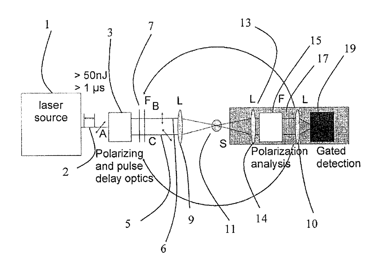
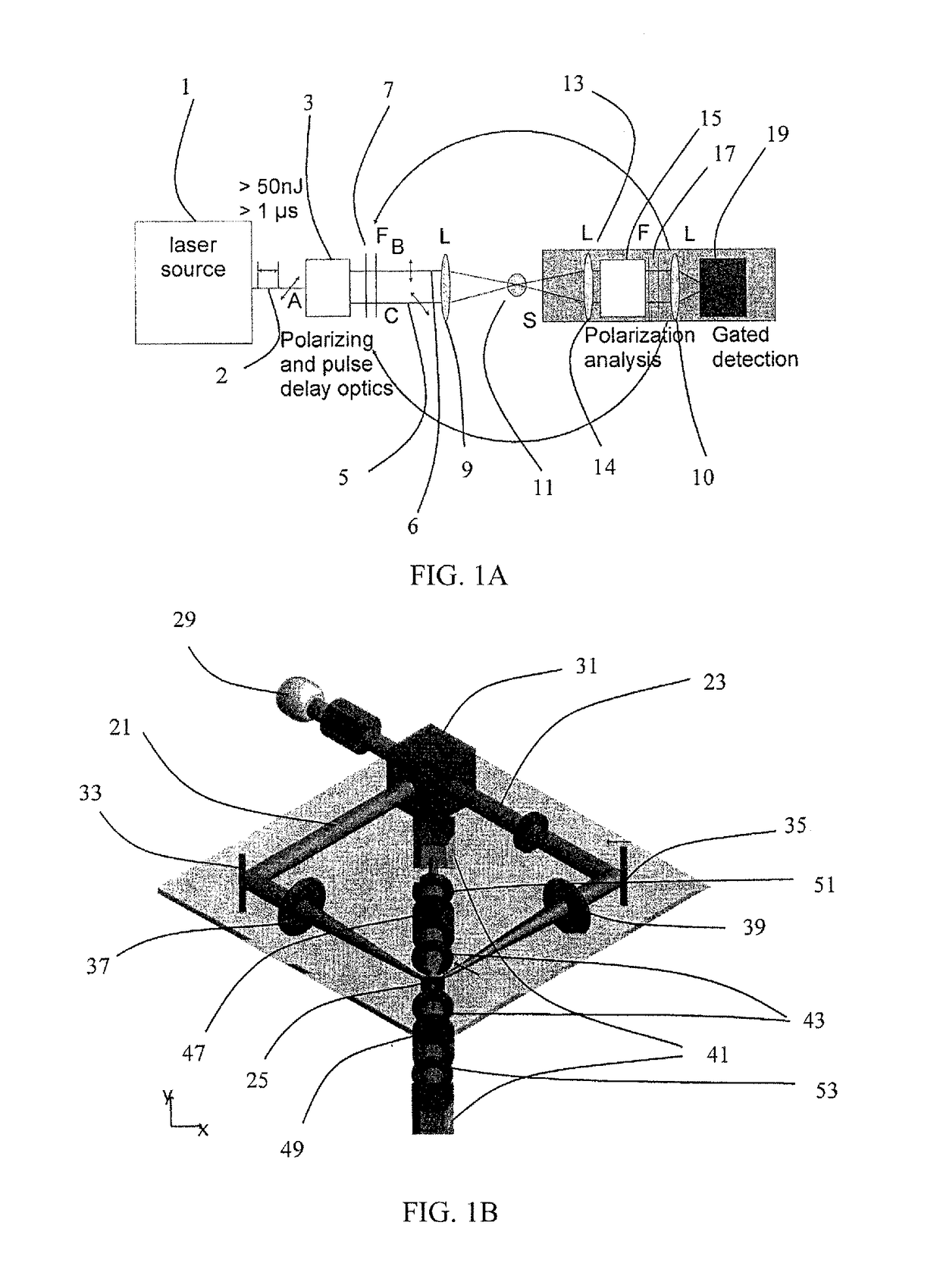
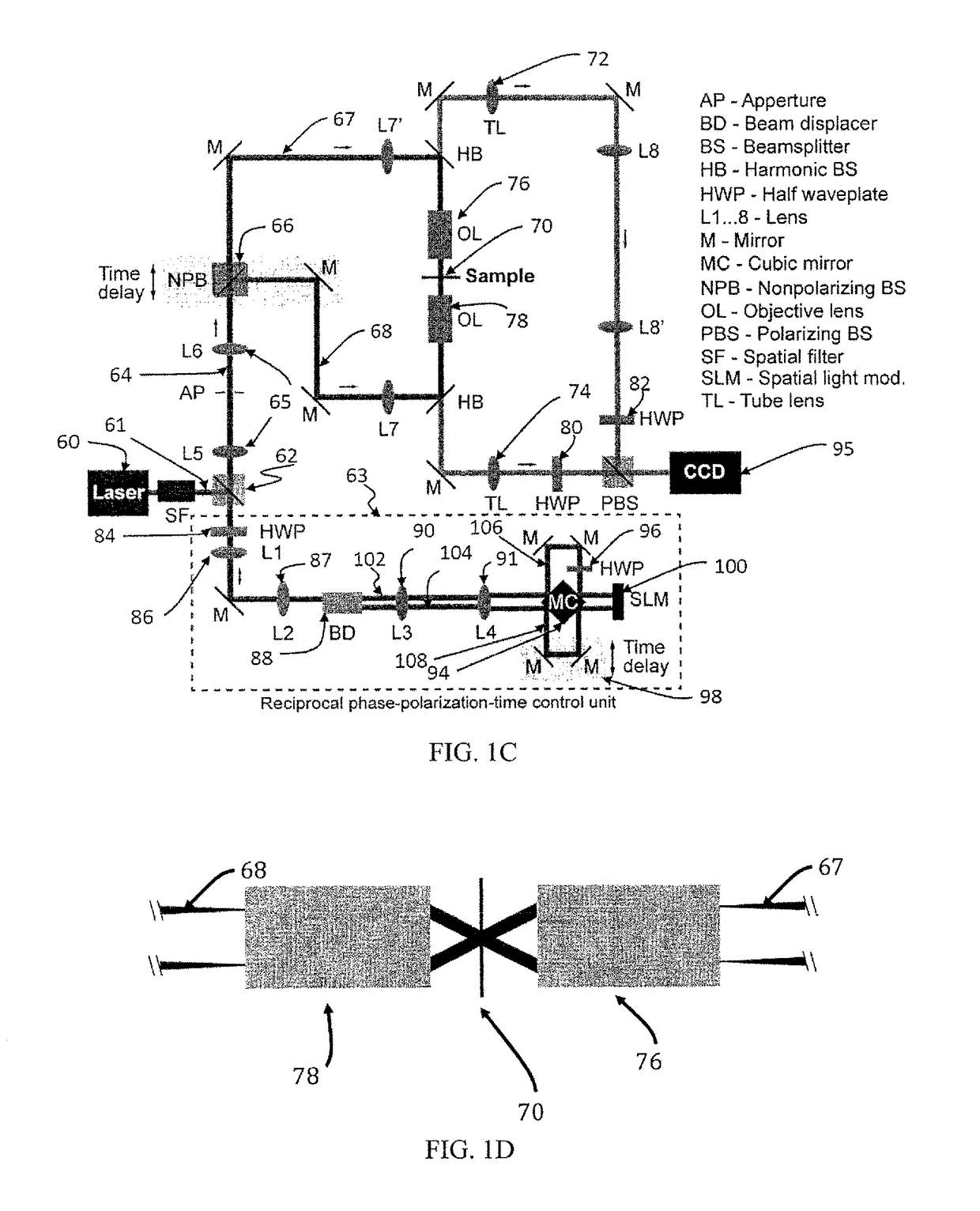
[0061]An example of an experimental optical setup for measuring second harmonic generation (SHG) scattered radiation from a sample is presented in FIG. 1A. It includes a laser source 1. In particular, the laser source is a laser system (Pharos, Light Conversion) delivering a beam 2 of femtosecond pulses with a repetition rate of f50 nJ. The beam 2 is split by a polarizing beam splitter 3 into a first partial beam 5 and a second partial beam 6. The partial beams have different states of polarization, preferably perpendicular states of polarization. Furthermore, means (not shown) that are arranged to controllably vary the path length of at least one of the partial beams 5, 6 and means to control or change the state of polarization of at least one of the partial beams 5, 6, and means to control or change the phase of at least one of the partial beams 5, 6, and means to control or change ...


PUM

PropertyMeasurementUnit
pulse energyaaaaaaaaaa
diameteraaaaaaaaaa

Abstract

Embodiments of the subject invention relate to a method and apparatus for performing measurements using multiphoton or second harmonic generation (SHG) scattered radiation from a sample including a turbid (scattering) medium includes providing a beam of laser pulses from a laser source having high pulse energies and a repetition rate; splitting the beam of laser pulses into two or more partial beams and focussing and overlaying the partial beams on a sample including the turbid medium; and detecting multiphoton and second harmonic radiation scattered from the sample.

Description

CROSS-REFERENCE TO RELATED APPLICATIONS[0001]The present application is a continuation-in-part of International Patent Application No. PCT / EP2013 / 064723, filed Jul. 11, 2013, which claims the benefit of European Patent Application No. 12 176 708.1, filed Jul. 17, 2012, both of which are hereby incorporated by reference herein in their entirety, including any figures, tables, or drawings.FIELD OF INVENTION[0002]The present invention relates to high-throughput nonlinear optical metrology and, in particular, to a device and a method for performing measurements and imaging with a high photon throughput using second harmonic generation (SHG) scattered radiation from a sample.BACKGROUND[0003]Many biological and chemical properties of nano- and micro-sized objects, such as particles, electrodes, implants, bubbles, droplets, viruses, micelles, liposomes and living cells are determined by processes occurring at the interface between the object and a medium surrounding or being in contact wit...

Claims


Application Information

Patent Timeline
Patent Type & Authority Patents(United States)
IPC IPC(8): G01N21/00G02F1/37G01N21/47G01N21/21G02B21/36G01N15/14
CPCG01N21/47G01N15/1434G01N21/21G02B21/361G02F1/37G01N2201/0683G01N2201/0697G01N2201/06113G01N21/636G01N21/49
Inventor ROKE, SYLVIEMACIAS ROMERO, CARLOS
Owner ECOLE POLYTECHNIQUE FEDERALE DE LAUSANNE (EPFL)
Why Eureka
Eureka Blog
Learn More