
Intramedullary fracture fixation devices and methods

a technology for fixing devices and fractures, applied in the field of devices, tools and methods for providing bone reconstruction and reinforcement, can solve the problems of multiple traumas and resultant fractures, large number of non-life-threatening fractures, and significant bone fractures, and achieve the effect of reducing distan

Active Publication Date: 2017-11-14
ARTHREX
View PDF769 Cites 37 Cited by
  • Summary
  • Abstract
  • Description
  • Claims
  • Application Information

AI Technical Summary

Benefits of technology

The patent text describes a method for repairing bone fractures using a special fixation device. The device has an expandable portion that is inserted into the bone marrow canal and a screw that is used to reduce the distance between the two fractured bone segments. The technique allows for a secure and minimally invasive repair of bone fractures.

Problems solved by technology

Lastly, the acceptance and ubiquitous application of passive restraint systems, airbags, in automobiles has created greater numbers of non-life threatening fractures.
In the past, a person that might expire from a serious automobile accident now survives with multiple traumas and resultant fractures.
However, with an increasingly aging population, osteoporosis has become more of a significant medical concern in part due to the risk of osteoporotic fractures.
Also, sports and work-related accidents account for a significant number of bone fractures seen in emergency rooms among all age groups.
This can take several months for the bone to heal and for the patient to remove the cast before resuming normal activities.
Invariably, this line of sight access violates, disrupts, and causes damage to important soft tissue structures such as ligaments, tendons, cartilage, fascia, and epidermis.
Further, micro-motion between the bone and the IM nail may cause pain or necrosis of the bone.
This requires a subsequent surgery with all of the complications and risks of a later intrusive procedure.
In general, rigid IM rods or nails are difficult to insert, can damage the bone and require additional incisions for cross-screws to attach the rods or nails to the bone.

Method used


Image

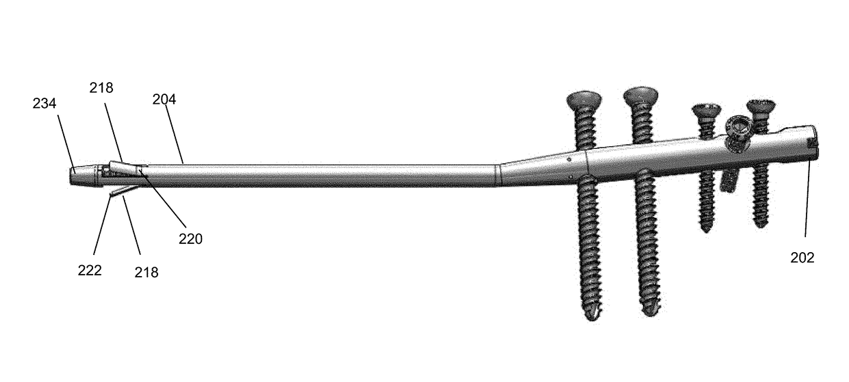
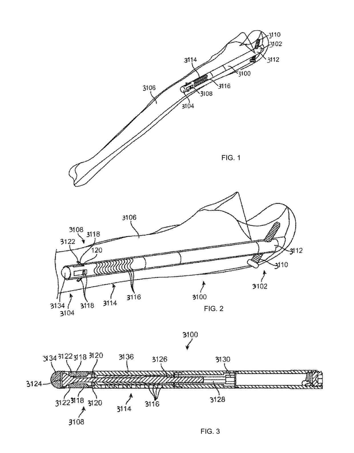
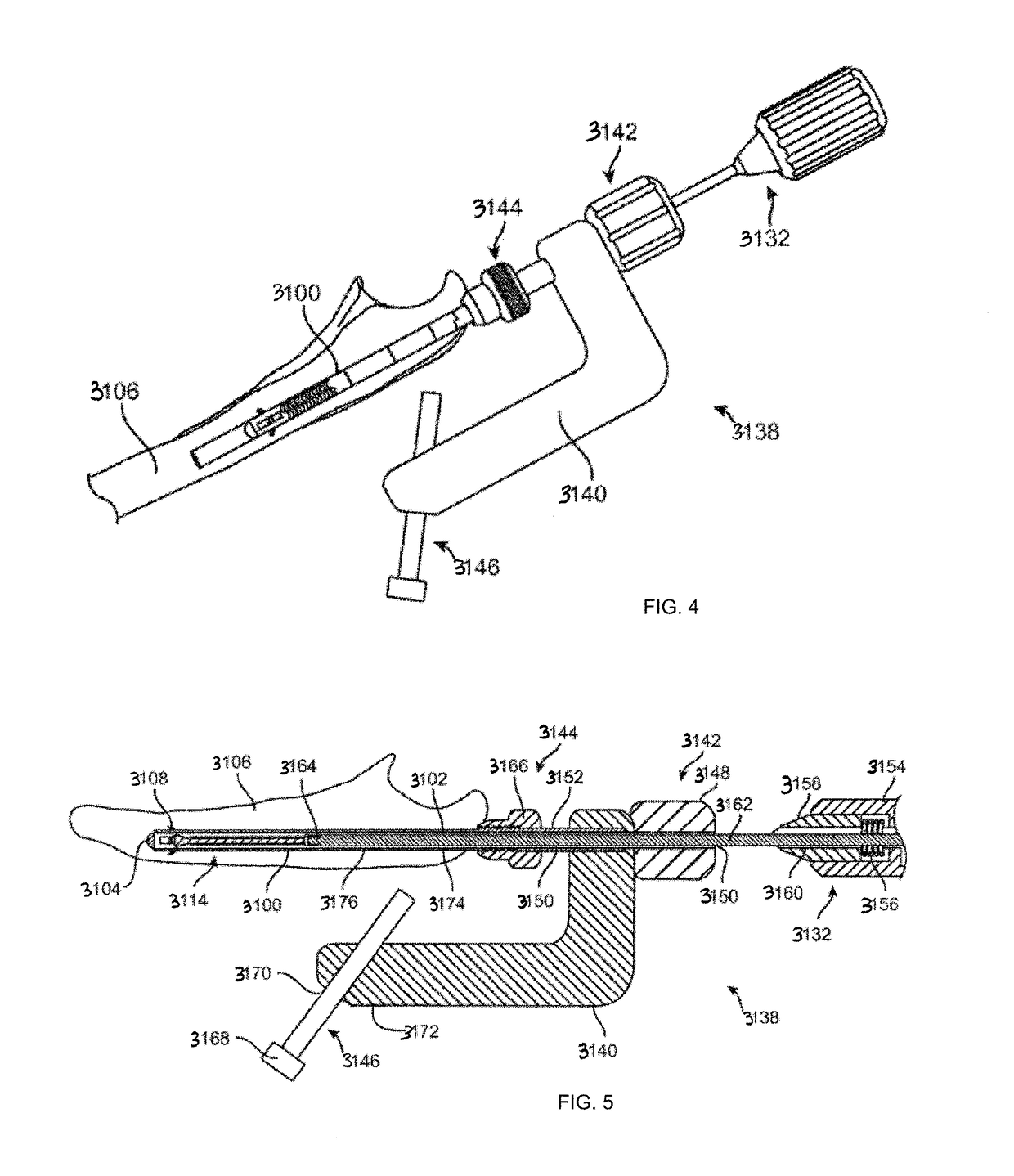
  • Intramedullary fracture fixation devices and methods
  • Intramedullary fracture fixation devices and methods
  • Intramedullary fracture fixation devices and methods

Examples


Embodiment Construction

[0081]By way of background and to provide context for the invention, it may be useful to understand that bone is often described as a specialized connective tissue that serves three major functions anatomically. First, bone provides a mechanical function by providing structure and muscular attachment for movement. Second, bone provides a metabolic function by providing a reserve for calcium and phosphate. Finally, bone provides a protective function by enclosing bone marrow and vital organs. Bones can be categorized as long bones (e.g. radius, femur, tibia and humerus) and flat bones (e.g. skull, scapula and mandible). Each bone type has a different embryological template. Further each bone type contains cortical and trabecular bone in varying proportions. The devices of this invention can be adapted for use in any of the bones of the body as will be appreciated by those skilled in the art.

[0082]Cortical bone (compact) forms the shaft, or diaphysis, of long bones and the outer shell...


PUM


Abstract

An intramedullary bone fixation device is provided with an elongate body having a longitudinal axis and an actuator to deploy at least one gripper to engage an inner surface of the intramedullary space to anchor the fixation device to the bone. Methods of repairing a fracture of a bone are also disclosed. One such method comprises inserting a fixation device into an intramedullary space of the bone to place at least a portion of the fixation device on one side of the fracture, providing rigidity across the fracture, and operating an actuator to deploy at least one gripper to engage an inner surface of the intramedullary space to anchor the fixation device to the bone. Various configurations allow a segmented device body to lock in the intramedullary space before and / or after fixation of the bone.

Description

INCORPORATION BY REFERENCE[0001]The present application claims priority under 35 U.S.C. §119(e) to U.S. Provisional Application No. 62 / 057,913 filed on Sep. 30, 2014, the disclosures of this application is incorporated by reference herein in its entirety. All publications and patent applications mentioned in this specification are herein incorporated by reference in their entirety to the same extent as if each individual publication or patent application was specifically and individually indicated to be incorporated by reference. For example, U.S. patent application Ser. No. 13 / 615,078, filed Sep. 13, 2012 is incorporated by reference in its entirety, including all applications to which it claims priority. For example, U.S. patent application Ser. No. 13 / 614,523, filed Sep. 13, 2012 is incorporated by reference in its entirety, including all applications to which it claims priority.BACKGROUND OF THE INVENTION[0002]Field of the Invention[0003]Embodiments of the present invention rela...

Claims


Application Information

Patent Timeline
Patent Type & Authority Patents(United States)
IPC IPC(8): A61B17/72A61B17/84A61B17/68A61B17/17A61B17/86A61B90/00
CPCA61B17/7233A61B17/1725A61B17/683A61B17/7266A61B17/848A61B17/86A61B17/7208A61B2090/031
Inventor BUSCAGLIA, ALEXANDER CARLOCARPENTER, BRIAN BRADFORDLAPPIN, KYLE EDWARDMCDANIEL, STEPHEN RIDDLEPAREKH, SELENE GUNVANTPHILBIN, TERRENCE MICHAELTONKS, ROBERT DEANFLETCHER, DARRYLL LEONARD CHARLES
Owner ARTHREX
Learn More