Multi-coated anodized wire and method of making same

a technology of anodized wire and anodized conductor, which is applied in the direction of insulated conductors, inorganic insulators, cables, etc., can solve the problems of poor operating performance, ineffective dissipation of ohmic or resistance heating, and being too brittle for most applications, so as to achieve high voltage and high temperature operation

Active Publication Date: 2017-11-14
FORD GLOBAL TECH LLC
View PDF17 Cites 2 Cited by
  • Summary
  • Abstract
  • Description
  • Claims
  • Application Information

AI Technical Summary

Benefits of technology

[0008]The electric conductor of the disclosed invention may be useful in a broad variety of applications where coiled wire or similar conductive material is required, such as for vehicle generators, alternators and for subsystems related to generators, alternators and regulators. Accordingly, the disclosed invention may be useful in the manufacture of both internal combustion vehicles as well in hybrid vehicles and systems for hybrid vehicles. Furthermore, the disclosed invention may find application in any electrical motor that requires very high voltage, effective heat dissipation and high temperature operation. Accordingly, the disclosed invention may find application in the locomotive and aerospace industries as well as in the automotive vehicle industry.

Problems solved by technology

However, while these materials demonstrate good dielectric properties and have the ability to withstand high voltages, they are compromised by their poor operating performance at temperatures above 220° C. as well as by their failure to effectively dissipate ohmic or resistance heating when used in coil windings.
(Inorganic insulation such as glass, mica or certain ceramics, tolerates temperatures greater than 220° C. but suffers from being too brittle for most applications.)
In the case of a copper core, the anodization of this material is known to produce unsatisfactory results due to cracking.
It is possible to electroplate copper with aluminum but this approach generally produces undesirable results in terms of durability of the coating.
In the case of an aluminum core, copper can be plated on the core but results in unsatisfactory electrical efficiency.

Method used


Image

  • Multi-coated anodized wire and method of making same
  • Multi-coated anodized wire and method of making same
  • Multi-coated anodized wire and method of making same

Examples


Embodiment Construction

[0016]In the following figures, the same reference numerals will be used to refer to the same components. In the following description, various operating parameters and components are described for different constructed embodiments. These specific parameters and components are included as examples and are not meant to be limiting.

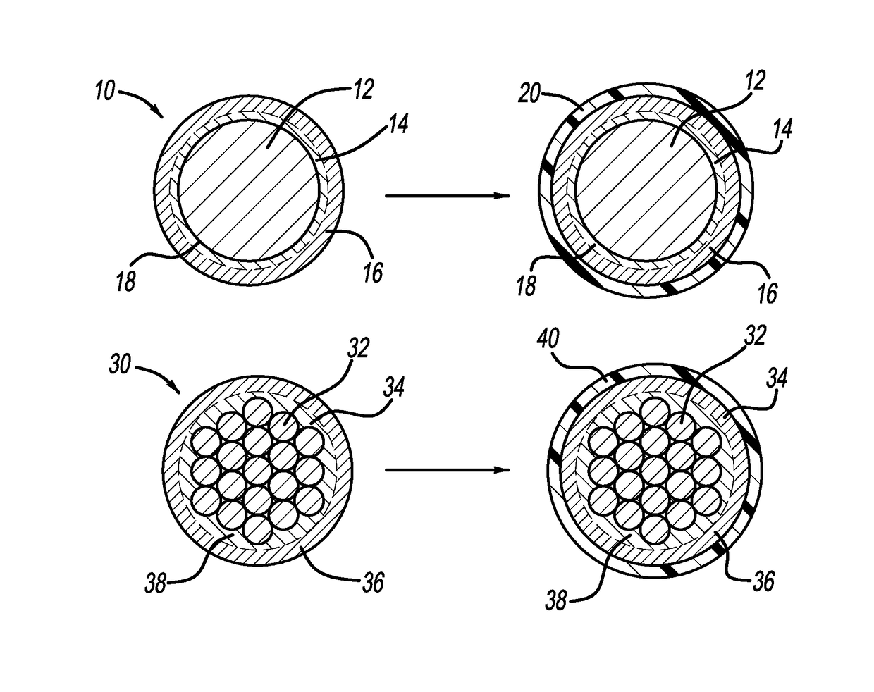
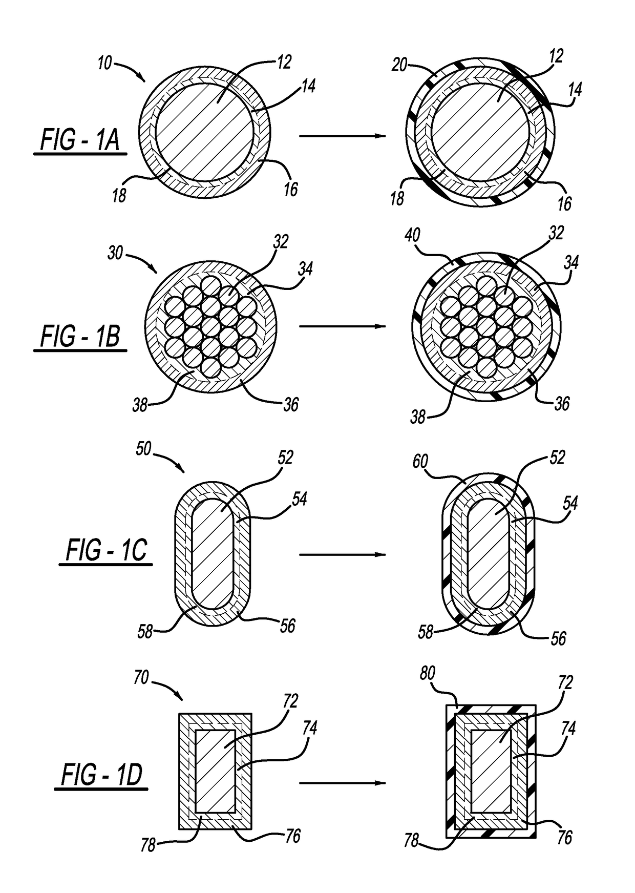
[0017]With respect to FIGS. 1A-1D, sectional views of wires and related electrical composite conductors illustrated before and after being overcoated with a thin layer of high-purity aluminum according to the disclosed invention are illustrated. The wires and related conductors are preferably although not necessarily formed according to the methods and materials set forth in U.S. Pat. No. 7,572,980 incorporated by reference in its entirety herein. The '980 patent is assigned to the same assignee to which the disclosed invention is assigned.

[0018]With particular reference to FIG. 1A, a sectional view of a composite conductor, generally illustrated as 10, is ...


PUM

PropertyMeasurementUnit
temperaturesaaaaaaaaaa
electrically conductiveaaaaaaaaaa
dielectric electrically insulatingaaaaaaaaaa

Abstract

An insulated electric conductor having a copper core, a layer of aluminum formed on the copper core, and a second layer of aluminum in the form of high-purity aluminum is disclosed. The copper core may be a solid core or may be formed from a plurality of copper strands. The layer of aluminum formed over the copper core is at least partially anodized to form an aluminum oxide dielectric layer. The layer of high-purity aluminum may be formed by evaporation deposition, sputter deposition, or co-extrusion. Once the layer of high-purity aluminum is formed, it is anodized. More than two layers of aluminum may be formed over the copper core.

Description

TECHNICAL FIELD[0001]The disclosed invention relates generally to an anodized conductor and method of making the anodized conductor. More particularly, the disclosed invention relates to a composite conductor having a copper core and an anodized aluminum dielectric layer overcoated with a second anodized aluminum layer and method for making same through post-metallic coating.BACKGROUND OF THE INVENTION[0002]The insulation of electrically conductive wire used to form a coil or similar conductive article is generally established and may be undertaken by a number of methods, including the fundamental approaches of coating with an organic polymerized material or anodization. With respect to the first approach, any one of several organic wire coatings selected from the group consisting of plastics, rubbers and elastomers will provide effective insulation on conductive material. However, while these materials demonstrate good dielectric properties and have the ability to withstand high vo...

Claims


Application Information

Patent Timeline
Patent Type & Authority Patents(United States)
IPC IPC(8): H01B7/00C25D11/18H01B3/10C25D11/04C25D11/12H01B1/02
CPCH01B3/105C25D11/04C25D11/18H01B1/026C25D11/12H01B7/0009
Inventor ELIE, LARRY DEANGALE, ALLAN ROYGINDER, JOHN MATTHEWMARANVILLE, CLAY WESLEY
Owner FORD GLOBAL TECH LLC
Why Eureka
Try Eureka