Liquid-cooled-type cooling device and manufacturing method for same

a cooling device and liquid cooling technology, applied in the direction of manufacturing tools, semiconductor/solid-state device details, lighting and heating apparatus, etc., can solve the problems of insufficient heat radiation performance, insufficient dimensional accuracy of pin-shaped fins in height, inability to make pin-shaped fin height uniform, etc., to achieve uniform height of pin-shaped fins, improve heat transfer between heat-generating bodies and pin-shaped fins, and improve the effect of dimensional accuracy

Active Publication Date: 2017-12-19
RESONAC CORPORATION
View PDF38 Cites 4 Cited by
  • Summary
  • Abstract
  • Description
  • Claims
  • Application Information

AI Technical Summary

Benefits of technology

[0004]An object of the present invention is to solve the above-mentioned problem and to provide a liquid-cooled-type cooling device which can improve heat radiation performance and can suppress an increase in the number of man-hours required for manufacturing the liquid-cooled-type cooling device, and a method of manufacturing the same.
[0018]The liquid-cooled-type cooling device of any one of pars. 1) to 6) comprises a casing which has a top wall and a bottom wall and in which a cooling-liquid passage is provided; and a radiating member disposed in the cooling-liquid passage within the casing. The radiating member is composed of a substrate and a plurality of pin-shaped fins which are oriented such that their longitudinal direction coincides with a vertical direction and whose longitudinally intermediate portions are brazed to the substrate. A plurality of fin insertion holes are formed in the substrate. The pin-shaped fins are inserted into the fin insertion holes of the substrate. The pin-shaped fins and the substrate are brazed together in a state in which the pin-shaped fins and the substrate are provisionally fixed by plastic deformation of at least the pin-shaped fins or portions of the substrate around the fin insertion holes. Upper and lower end portions of the pin-shaped fins are brazed to the top wall and bottom wall, respectively, of the casing. Therefore, the pin-shaped fins can be formed separately from the substrate, and the dimensional accuracy of the pin-shaped fins is improved, whereby the heights of the pin-shaped fins can be made uniform. Also, since the upper and lower end portions of the pin-shaped fins are brazed to the top and bottom walls of the casing, the following advantageous effect is attained. In the case where a heat-generating body is attached to the outer surface of at least one of the top and bottom walls of the casing, of the top and bottom walls, the wall to which the heat-generating body is attached can be made thin as compared with the substrate of the heat sink of the liquid-cooled-type cooling device disclosed in Japanese Patent Application Laid-Open No. 2009-277768, whereby transfer of heat between the heat-generating body and the pin-shaped fins is improved. Accordingly, the liquid-cooled-type cooling device has an enhanced heat radiation performance. In addition, since the upper and lower end portions of the pin-shaped fins are brazed to the top and bottom walls of the casing, even in the case where the top or bottom wall to which the heat-generating body is attached is made thinner than the substrate of the heat sink of the liquid-cooled-type cooling device disclosed in the publication, the liquid-cooled-type cooling device has an increased withstanding pressure.
[0019]According to the method of manufacturing a liquid-cooled-type cooling device of any one of pars. 7) to 12), since the pin-shaped fins can be formed separately from the substrate and the dimensional accuracy of the pin-shaped fins is improved, the heights of the pin-shaped fins in a manufactured liquid-cooled-type cooling device can be made uniform. Also, since the upper and lower end portions of the pin-shaped fins are brazed to the top and bottom walls of the casing in a state in which the pin-shaped fins are provisionally fixed to the substrate, positional shift of the pin-shaped fins at the time of brazing can be prevented. Furthermore, since the upper and lower end portions of the pin-shaped fins are brazed to the top and bottom walls of the casing, the following advantageous effect is attained. In the case where a heat-generating body is attached to the outer surface of at least one of the top and bottom walls of the casing of the manufactured liquid-cooled-type cooling device, of the top and bottom walls, the wall to which the heat-generating body is attached can be made thin as compared with the substrate of the heat sink of the liquid-cooled-type cooling device disclosed in Japanese Patent Application Laid-Open No. 2009-277768, whereby transfer of heat between the heat-generating body and the pin-shaped fins is improved. Accordingly, the liquid-cooled-type cooling device has an enhanced heat radiation performance. In addition, since the upper and lower end portions of the pin-shaped fins are brazed to the top and bottom walls of the casing, even in the case where the top or bottom wall to which the heat-generating body is attached is made thinner than the substrate of the heat sink of the liquid-cooled-type cooling device disclosed in the publication, the manufactured liquid-cooled-type cooling device has an increased withstanding pressure.

Problems solved by technology

However, in the case of the liquid-cooled-type cooling device disclosed in the publication, since the pin-shaped fins of the radiating member are integrally formed on the substrate through forging, their dimensional accuracy in the height direction is insufficient.
Therefore, the pin-shaped fins cannot be made uniform in height.
In such a case, after formation of the pin-shaped fins, the substrate has a relatively large thickness, which lowers the transfer of heat from a heat-generating body attached to the second surface to the pin-shaped fins, whereby the heat radiation performance becomes insufficient.
However, in this case, the number of man-hours required for manufacturing the liquid-cooled-type cooling device increases.
In addition, since the distal ends of the pin-shaped fins are not joined to the bottom wall, when the thickness of the substrate is decreased, the withstanding pressure of the liquid-cooled-type cooling device may become insufficient.

Method used


Image

  • Liquid-cooled-type cooling device and manufacturing method for same
  • Liquid-cooled-type cooling device and manufacturing method for same
  • Liquid-cooled-type cooling device and manufacturing method for same

Examples


Embodiment Construction

[0032]An embodiment of the present invention will next be described with reference to the drawings.

[0033]In the specification and appended claims, the term “aluminum” encompasses aluminum alloys in addition to pure aluminum.

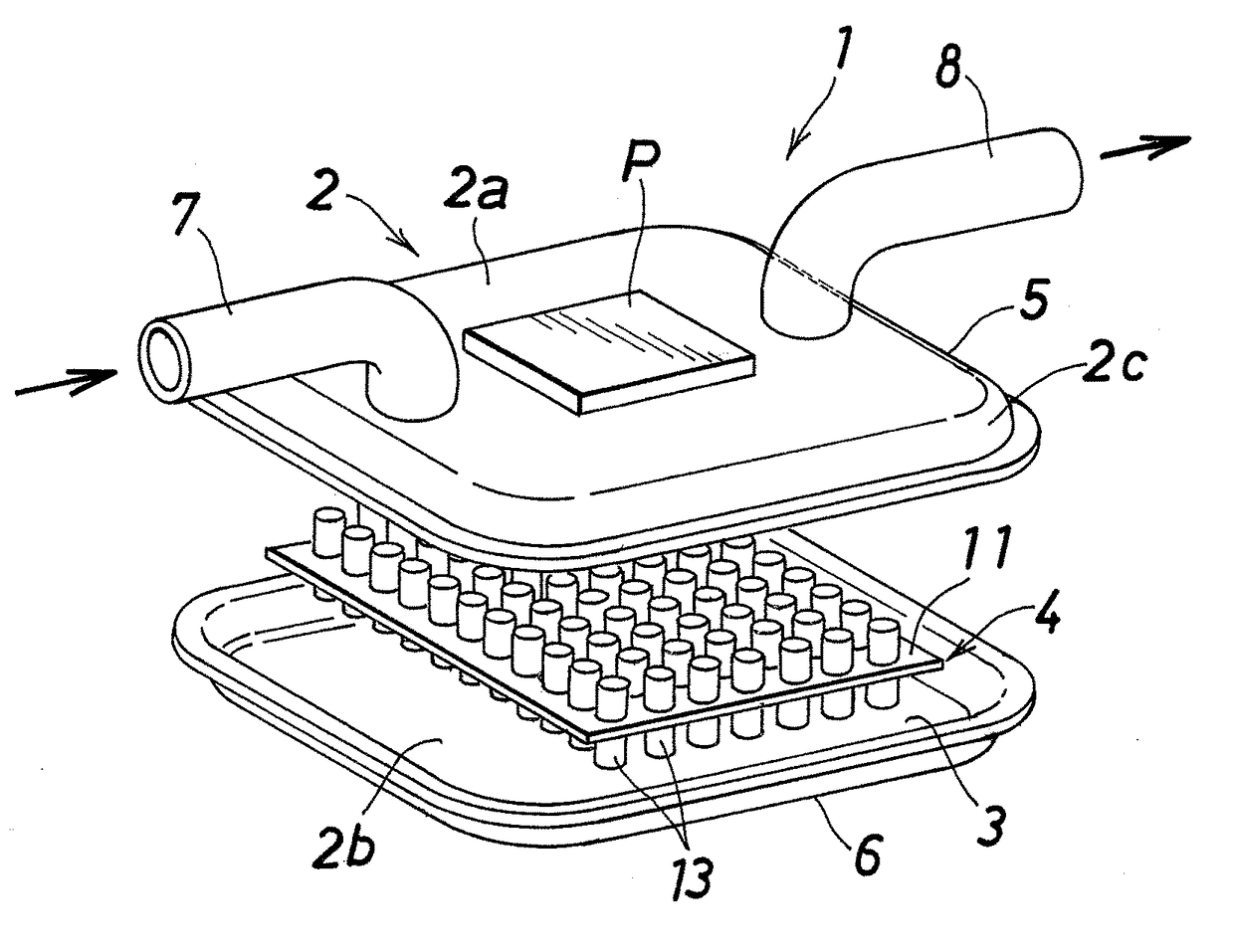
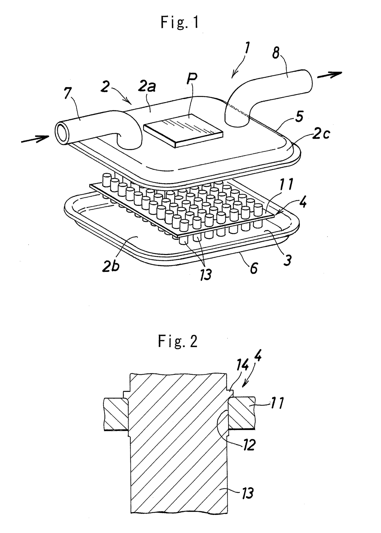
[0034]FIG. 1 shows the overall structure of a liquid-cooled-type cooling device according to the present invention; and FIG. 2 shows the structure of a main portion of the liquid-cooled-type cooling device.

[0035]As shown in FIG. 1, a liquid-cooled-type cooling device 1 includes a hollow casing 2 and a radiating member 4. The casing 2 has a top wall 2a, a bottom wall 2b, and a peripheral wall 2c, and a cooling-liquid passage 3 is provided within the casing 2. The radiating member 4 is disposed in the cooling-liquid passage 3 within the casing 2.

[0036]The casing 2 is formed by brazing together an upper constituent member 5 which is made of aluminum and which constitutes the top wall 2a and the upper half of the peripheral wall 2c, and a lower constituent member 6 w...


PUM

PropertyMeasurementUnit
diameteraaaaaaaaaa
diameteraaaaaaaaaa
depthaaaaaaaaaa

Abstract

A liquid-cooled-type cooling device includes a casing having a top wall, a bottom wall, and a cooling-liquid passage, and a radiating member disposed in the cooling-liquid passage. The radiating member has a substrate and a plurality of pin-shaped fins. Longitudinally intermediate portions of the pin-shaped fins are brazed to the substrate. The substrate has a plurality of fin insertion holes, and the pin-shaped fins are inserted into the fin insertion holes of the substrate. A plurality of convex portions are integrally formed on the longitudinally intermediate portion of each pin-shaped fin. The substrate and the pin-shaped fins are provisionally fixed together by plastically deforming the convex portions such that they are crushed. In this state, the substrate and the pin-shaped fins are brazed together. The upper and lower end portions of the pin-shaped fins are brazed to the top wall and bottom wall, respectively, of the casing.

Description

BACKGROUND OF THE INVENTION[0001]The present invention relates to a liquid-cooled-type cooling device for cooling a heat-generating body composed of an electronic component such as a semiconductor device, and to a method of manufacturing the same.[0002]The present applicant has proposed a liquid-cooled-type cooling device for cooling a power device (semiconductor device), such as IGBT (Insulated Gate Bipolar Transistor), which is used in a power conversion apparatus mounted on an electric vehicle, a hybrid vehicle, an electric railcar, or the like (see Japanese Patent Application Laid-Open (kokai) No. 2009-277768). The proposed liquid-cooled-type cooling device includes a casing having a cooling-liquid passage through which cooling liquid, including water (e.g., long life coolant) flows, and a radiating member fitted into an opening formed in the top wall of the casing. The radiating member is composed of a substrate whose first surface faces the cooling-liquid passage and whose sec...

Claims


Application Information

Patent Timeline
Patent Type & Authority Patents(United States)
IPC IPC(8): F28F3/12B23P15/26F28F1/40H01L23/473B23P11/00F28F3/02F28F21/08
CPCF28F1/40B23P11/00B23P15/26F28F3/022F28F3/12F28F21/084H01L23/473Y10T29/4935F28F2275/04F28F2275/12H01L2924/0002H01L2924/00H01L23/34H05K7/20
Inventor MATSUSHIMA, SEIJITOMITA, KOUJI
Owner RESONAC CORPORATION
Why Eureka
Try Eureka