Backplane device

a backplane and circuit technology, applied in static indicating devices, electrical appliances, instruments, etc., can solve the problems of high frequency signals being applied to addressing lines of pixel circuitries, and achieve the effect of simplifying the driving method

Active Publication Date: 2018-01-02
SEEREAL TECHNOLOGIES
View PDF22 Cites 0 Cited by
  • Summary
  • Abstract
  • Description
  • Claims
  • Application Information

AI Technical Summary

Benefits of technology

[0013]It is therefore an object of the present invention to overcome at least one drawback mentioned above, especially in providing a simpler driving method.

Problems solved by technology

This most likely will result in high frequency signals being applied to addressing lines of the pixel circuitries.

Method used


Image

  • Backplane device
  • Backplane device
  • Backplane device

Examples


Embodiment Construction

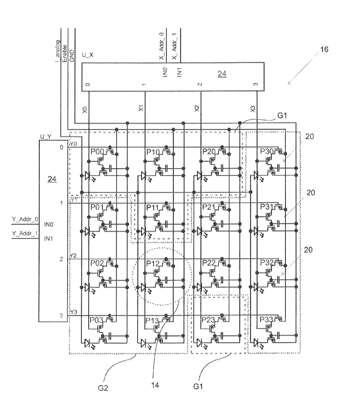
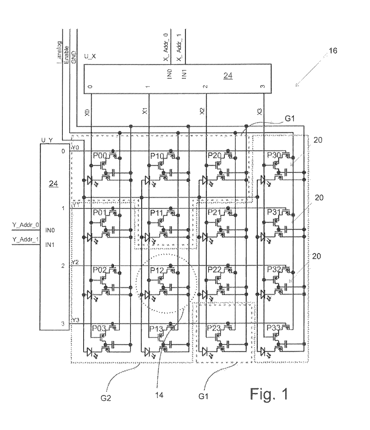
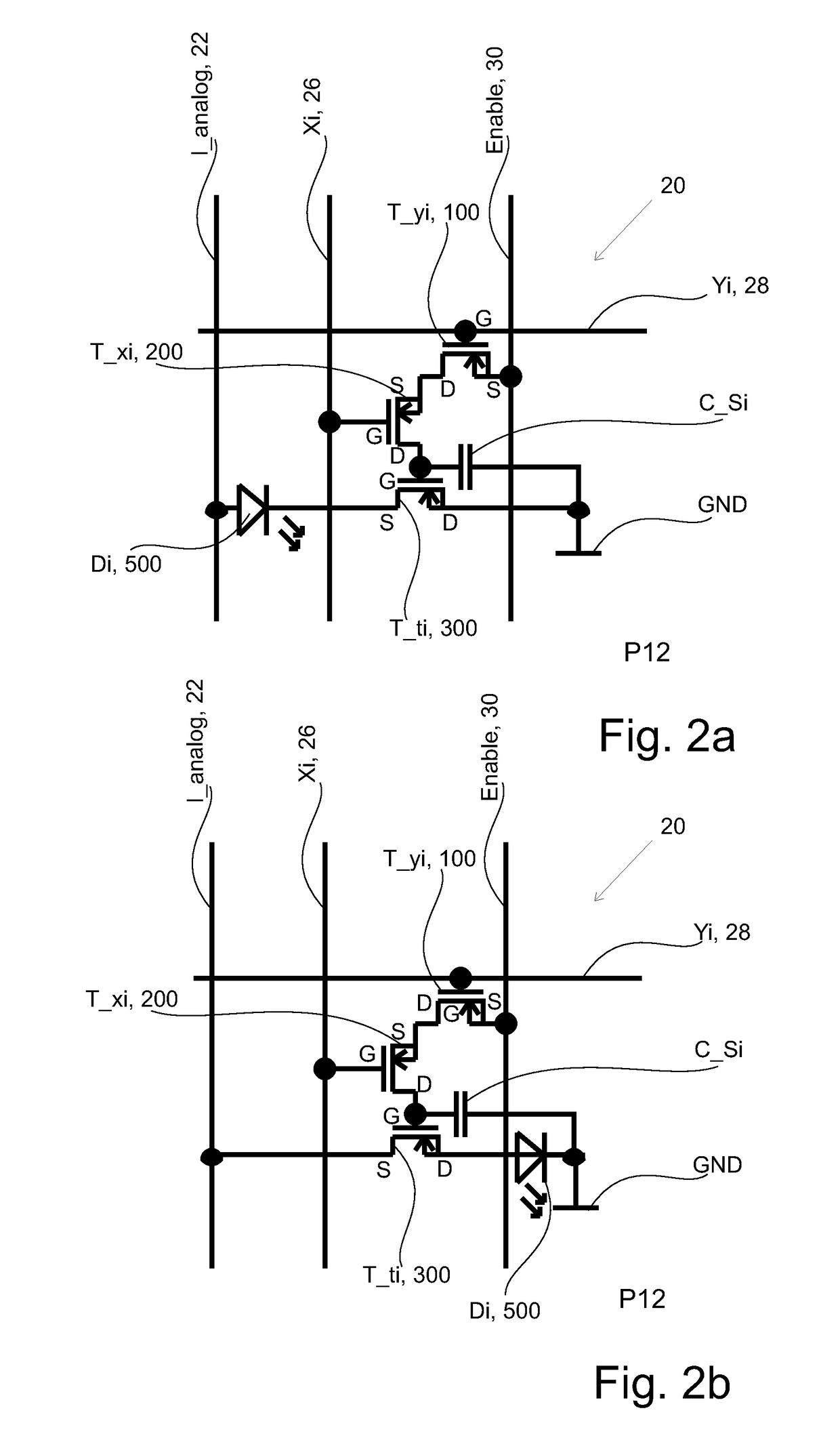
[0071]In an embodiment of the present invention, a backplane device using a 3-TFT approach is used (1 dual gate selection TFT+1 transfer TFT). Compared to a 3-TFT LC backplane setup for a spatial light modulator as described in EP10156572.9 or in PCT / EP / 2011 / 053912, an OLED is inserted instead of the pixel capacity. Accordingly, the basic principle of the backplane device disclosed in EP10156572.9 or in PCT / EP / 2011 / 053912 can be applied to the backplane device for the light source array or light source matrix according to the present invention. Therefore, the entire content of the documents EP10156572.9 or PCT / EP / 2011 / 053912 is incorporated herein by reference.

[0072]For the backplane according to the present invention the voltage source connected to the analog line is replaced by a current source. The TFTs are switching only digital, such there is no analog feedback into the pixel or into the circuitry of the pixel. The current flow is not regulated in the pixel circuit but thru out...


PUM


Abstract

The present invention relates to a backplane device for a light source matrix. A light source is preferably a LED or an OLED. A pixel circuitry of the backplane device is assigned to a light source of the light source matrix for controlling the light source. One light source and one pixel circuitry constitute a pixel. The pixels of the light source matrix are classified according to a pixel characteristic. The order of switching the light sources on and/or off depends on the pixel characteristic and not necessarily on the location of the pixel on the backplane device. A current being applied to the light sources is controlled by at least one driver. The at least one driver is electrically connectable to at least one pixel. The at least one driver is not belonging to the pixel circuitry of the pixel.

Description

CROSS REFERENCE TO RELATED APPLICATIONS[0001]This application claims the priority of PCT / EP2011 / 065086, filed on Sep. 1, 2011, which claims priority to European Application No. 10174976.0, filed Sep. 1, 2010; European Application No. 11170254.4, filed Jun. 16, 2011, and European Application No. 11178551.5, filed Aug. 23, 2011, the entire contents of all of which are hereby incorporated in total by reference.BACKGROUND OF THE INVENTION[0002]The present invention relates to a backplane device for a light source array or for a light source matrix as well as a method of driving a backplane for a light source array or for a light source matrix. In particular, the present invention relates to a backplane device for an array or matrix of light sources being LEDs (Light Emitting Diodes) or OLEDs (Organic Light Emitting Diodes), which can be used for a display being suitable to display two-dimensional or three-dimensional information, images and scenes and video sequences. Backplane devices ...

Claims


Application Information

Patent Timeline
Patent Type & Authority Patents(United States)
IPC IPC(8): H05B33/08G09G3/20G09G3/325G09G3/3266G09G3/3283G03H1/02H05B44/00
CPCH05B33/08G09G3/2085G09G3/325G09G3/3266G09G3/3283H04N13/0285G09G3/2081G09G2330/021G03H2001/0212G09G2300/0809G09G2300/0814G09G2310/0213G09G2310/0218G09G2310/0221G09G2310/0227G09G2310/0259G09G2310/0262G09G2310/0272G09G2320/043H04N13/286H05B45/00H05B45/60H05B44/00
Inventor MISSBACH, ROBERT
Owner SEEREAL TECHNOLOGIES
Why Eureka
Try Eureka