

Pseudo resistance circuit and charge detection circuit
a technology of charge detection and resistance circuit, which is applied in the direction of network simulating resistance, one-port active network, solid-state devices, etc., can solve the problem of waveform distortion in the output signal, and achieve the effect of reducing temperature dependence and easy integration
- Summary
- Abstract
- Description
- Claims
- Application Information
AI Technical Summary
Benefits of technology
Problems solved by technology
Method used
Image

Examples
Embodiment Construction
[0050]Hereinafter, the present invention will be clarified through descriptions of specific preferred embodiments and examples of the present invention with reference to the drawings.
[0051]It is to be noted that the preferred embodiments described in this specification are merely examples, and the configurations in the preferred embodiments are able to be partly replaced or combined between different preferred embodiments.
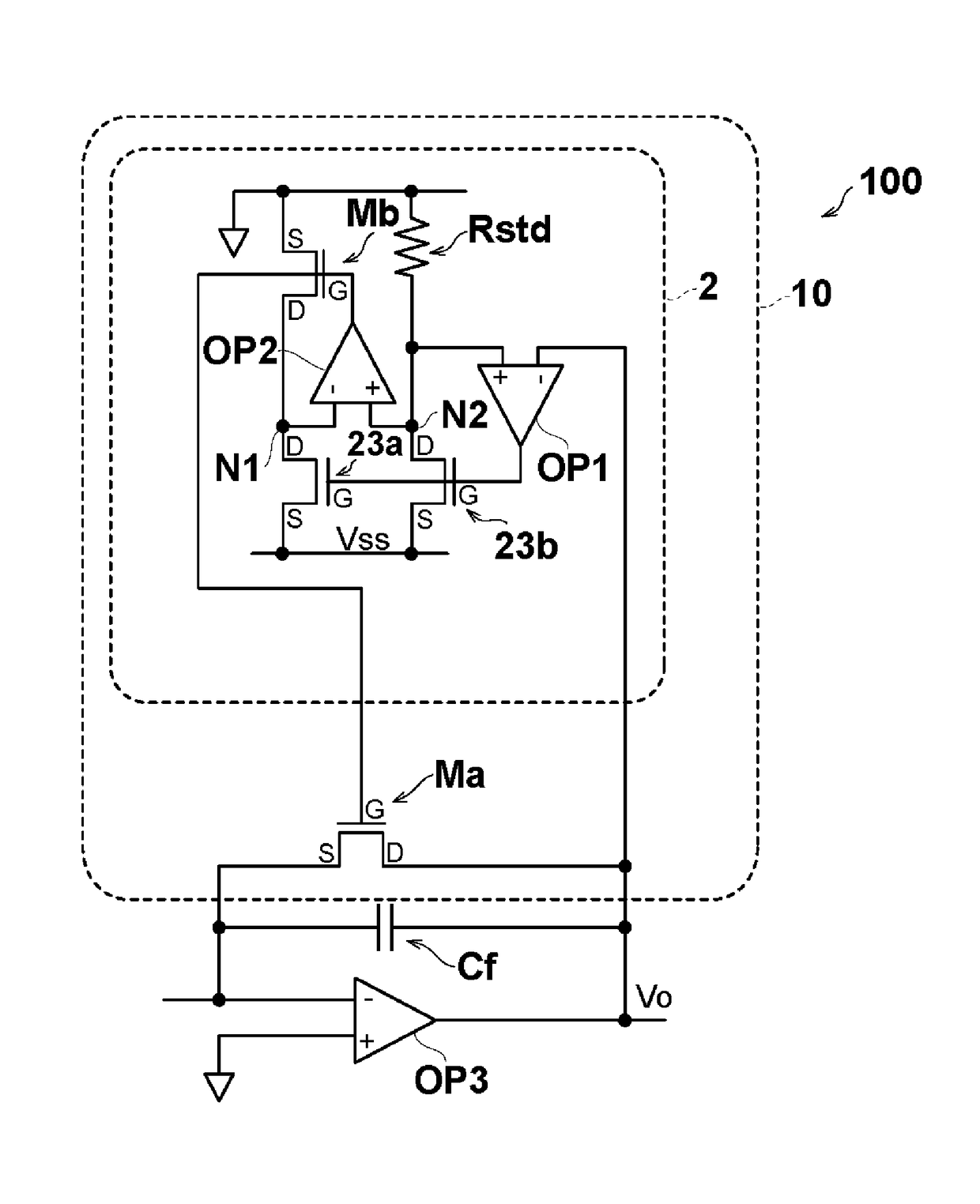
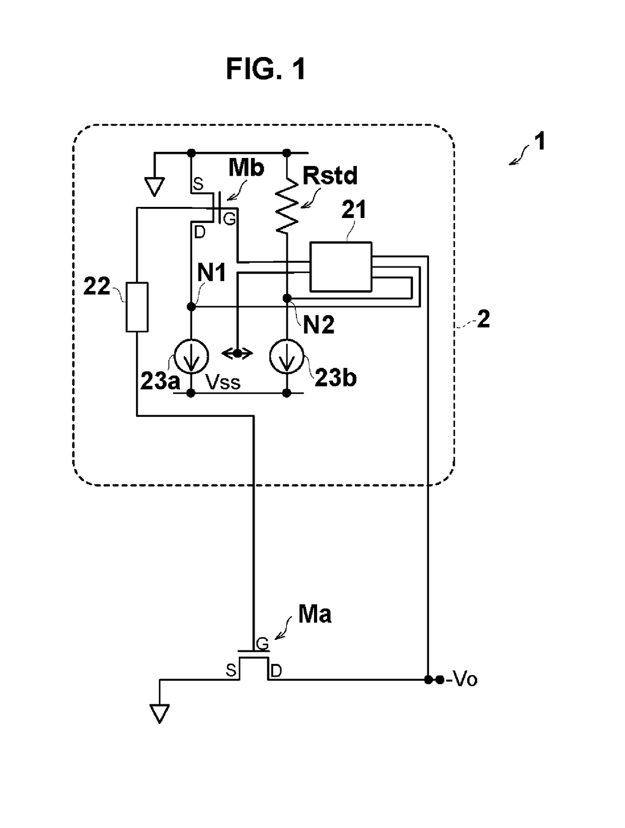
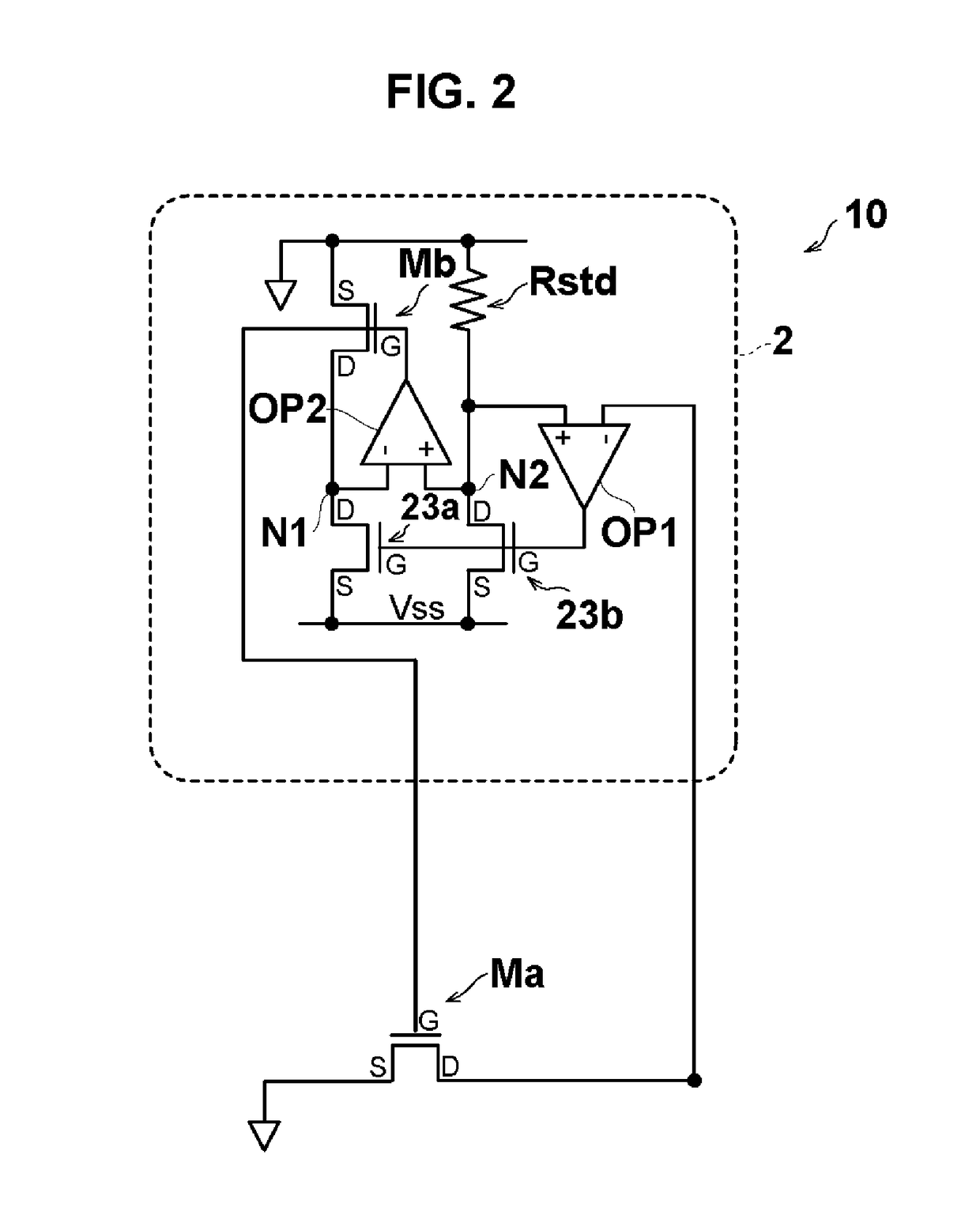
[0052]First, a pseudo resistance circuit 1 according to a preferred embodiment is described below with reference to FIG. 1.
[0053]FIG. 1 is a circuit diagram illustrating the pseudo resistance circuit 1.
[0054]As shown in FIG. 1, the pseudo resistance circuit 1 includes a first field effect transistor Ma and a distortion compensation bias source 2 that reduces waveform distortion due to a change in a resistance value of the first field effect transistor Ma.
[0055]The first field effect transistor Ma is a MOSFET, and, more specifically, is an n-type MOSFET. The first f...
PUM
 Abstract
Description
Claims
Application Information