Liquid crystal panel and the detection method on image sticking of the liquid crystal panel

a detection method and liquid crystal panel technology, applied in the field of liquid crystal panel and detection method, can solve the problems of inability to achieve the quality of the liquid crystal panel on time, the electrical resistance of the liquid crystal material cannot reach the standard, and the detection time is too long, so as to achieve the effect of reducing the defect rate, reducing the time for detecting the image sticking, and improving the detecting efficiency

Active Publication Date: 2018-02-06
TCL CHINA STAR OPTOELECTRONICS TECH CO LTD
View PDF12 Cites 0 Cited by
  • Summary
  • Abstract
  • Description
  • Claims
  • Application Information

AI Technical Summary

Benefits of technology

[0004]The main purpose of the present invention is to provided a liquid crystal panel and a detection method for rapidly detecting the image sticking.
[0013]Preferably, in step 4) saving the detected electric resistance and the metal ionic concentration of each test block, so as to trace the effect factors on the image sticking and the quality of the liquid crystal panel.
[0014]Compared to the prior art, the liquid crystal panel and the detection method on image sticking of the present invention, the electrical resistance and the metal ionic concentration of the small test block sample can be detected in advanced for determining the image sticking on the end product area of the liquid crystal panel whether exceeding out of the preset scope or not, so the time for detecting the image sticking will be great shorten. The detection result of the image sticking can be achieved seven days in advance, and then the detecting efficiency will be obviously improved, and the defect rate will be reduced, and the yield will be raise. Therefore, the product quality of the liquid crystal panel will be better to present more preferred displaying effect. With the detecting on the monochrome light resistance, the effect factors on the image sticking will be rapidly achieved and the waste on capacity and material from stratifying will be reduced. As a result, the related parameter and the quality of the liquid crystal on the same panel can be rapidly confirmed. The defective goods can be prohibited delivering rapidly.

Problems solved by technology

There are many effect factors on the image sticking, such as, bad in the design of the capacitance on the TFT actuator, the metal is sticking on the manufacture process, the electric resistance of the liquid crystal material is not reach the standard.
In the current detection methods, one of detection method is following: firstly, saving 168 hours the liquid crystal panel in a high-temperature and high-humidity condition; secondly, detecting the appearance effect for seven days, so the detecting time is too longer that the quality of the liquid crystal panel cannot be achieved on time.
If the image sticking is out of the standard, the reason of the image sticking shall be analyzed and traced by disassembling the liquid crystal panel or stratifying with a design experiment, so that it will bring wasting on capacity and material.

Method used


Image

  • Liquid crystal panel and the detection method on image sticking of the liquid crystal panel
  • Liquid crystal panel and the detection method on image sticking of the liquid crystal panel

Examples


first embodiment

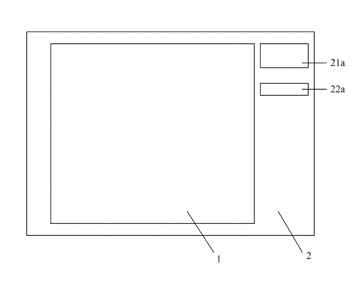
[0019]Referring to FIG. 1, in the first embodiment, a RGB test block 21a and a blank block 22a are provided in the test area 2, the RGB test block 21a is compounded with a red light resistance, a green light resistance and a blue light resistance. The electric resistance, the metal ionic concentration and the pixel of the RGB test block 21a is equal to that of the liquid crystal panel on the end product area 1, the electric resistance and the metal ionic concentration of the RGB test block 21a can be detected to determine whether the related target parameters of the liquid crystal panel on the end product area will reach the standard or not. The test block 2 is located at the right side of the end product area 1, which can be separated from the end product area 1 by cutting for separately detecting. The length of the RGB test block 21a and the blank block 22a is separated larger than 5 mm, and the width of each test block is separated larger than 3 mm.

[0020]The present invention is ...

second embodiment

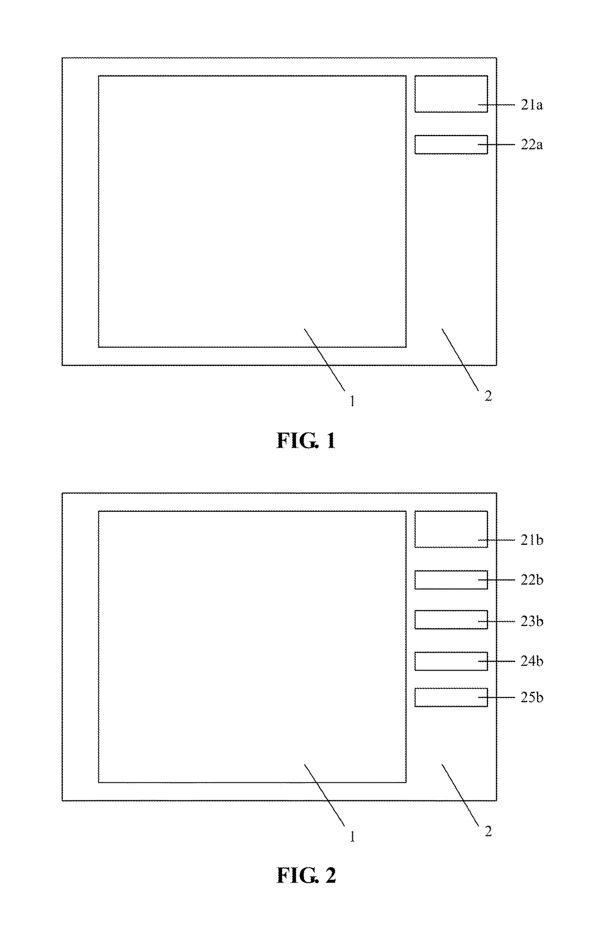
[0028]Referring to FIG. 2, in the second embodiment, a RGB test block 21b, a blank block 22b and three monochrome blocks are provided in the test area 2, the monochrome blocks comprises a red test block 23b, a green test block 24b and a blue test block 25b. The test area 2 is located at any side of the end product area 1. The RGB test block 21b, the blank block 22b, the red test block 23b, the green test block 24b and the blue test block 25b are align on a line. The RGB test block 23b is compounded with a red light resistance, a green light resistance and a blue light resistance. The test block 2 is located at the right side of the end product area 1, which can be separated from the end product area 1 by cutting for separately detecting. The length of each test block is separated larger than 5 mm, and the width of each test block is separated larger than 3 mm.

[0029]The present invention is also provided for a detection method on image sticking of the liquid crystal panel, which comp...


PUM

PropertyMeasurementUnit
widthaaaaaaaaaa
widthaaaaaaaaaa
electric resistanceaaaaaaaaaa

Abstract

A liquid crystal panel comprises an end product area and a test area, wherein a RGB test block, a blank block and three monochrome blocks are provided in the test area, the monochrome blocks comprises a red test block, a green test block and a blue test block, the RGB test block is compounded with a red light resistance, a green light resistance and a blue light resistance, the electric resistance and the metal ionic concentration of the RGB test block is equal to that of the end product area, the electric resistance and the metal ionic concentration can be determine whether the related target parameters of the liquid crystal panel on the end product area will reach the standard or not. Detection method on image sticking of the liquid crystal panel, the detecting efficiency will be obviously improved and the defect rate will be reduced.

Description

FIELD OF THE INVENTION[0001]The invention relates to a liquid crystal panel and a detection method, more particularly relates to a liquid crystal panel and the detection method on image sticking of the liquid crystal panel.BACKGROUND OF THE INVENTION[0002]Image sticking (IS) is a main detection project in the open cell process of the liquid crystal panel. There are many effect factors on the image sticking, such as, bad in the design of the capacitance on the TFT actuator, the metal is sticking on the manufacture process, the electric resistance of the liquid crystal material is not reach the standard. In the current detection methods, one of detection method is following: firstly, saving 168 hours the liquid crystal panel in a high-temperature and high-humidity condition; secondly, detecting the appearance effect for seven days, so the detecting time is too longer that the quality of the liquid crystal panel cannot be achieved on time. Another detection method is following: the liq...

Claims


Application Information

Patent Timeline
Patent Type & Authority Patents(United States)
IPC IPC(8): G01R31/26H04N17/02G02F1/13
CPCH04N17/02G02F1/1309G02F2203/69
Inventor ZHANG, YUEYANYANG, YI FENGLEE, CHIEN-PANG
Owner TCL CHINA STAR OPTOELECTRONICS TECH CO LTD
Why Eureka
Try Eureka